



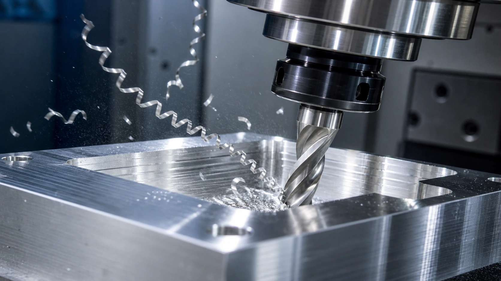
Praktische Einstiegsbereiche zum Fräsen, Bohren, klopfen, und Drehen von 6061-T6-Aluminium, mit Anleitung zur Werkzeugausstattung, Chipkontrolle, dünne Wände, Toleranzen, und Prozessvalidierung.
Einführung
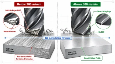
6061-T6 ist im Vergleich zu vielen technischen Metallen fehlerverzeihend, aber es belohnt dennoch einen disziplinierten Prozess. Ein scharfes Werkzeug kann Material schnell entfernen und eine saubere Oberfläche hinterlassen. Die gleiche Legierung kann auch Aufbauschneiden erzeugen, geschweißte Späne, Grate, Geschwätz, oder Maßabweichung beim Schneiden, Spanlast, Engagement, Kühlung, und Vorrichtung funktionieren nicht zusammen.
In diesem Leitfaden werden eher praktische Ausgangsmengen als Universalrezepte angegeben. Die endgültigen Parameter hängen vom Werkzeugdurchmesser und der Geometrie ab, Spindelleistung, maximale Drehzahl, Halterschlag, Werkzeugüberhang, radialer und axialer Eingriff, Kühlmittelzufuhr, Werkstückhalterung, Merkmalstiefe, und die erforderliche Oberfläche bzw. Toleranz. Verwenden Sie als primäre Referenz die Schnittdaten des Werkzeugherstellers, Bestätigen Sie anschließend den Vorgang mit kontrollierten Probeschnitten.
Für einen umfassenderen Material- und Designüberblick, siehe JADE-CNCs 6061-CNC-Bearbeitungsführung aus T6-Aluminium. Die folgenden Abschnitte konzentrieren sich auf die Parameterauswahl und die Prozesssteuerung in der Werkstatt.
Warum 6061-T6-Maschinen gut
6061-T6 kombiniert moderate Härte, nützliche Stärke, gute Wärmeleitfähigkeit, und relativ geringe Schnittkräfte. Es bilden sich meist handhabbare Späne mit scharfen Kanten, Werkzeuge mit positivem Spanwinkel. Diese Eigenschaften unterstützen hohe Materialabtragsraten und eine gute Oberflächenqualität ohne das starke Kaltverfestigungsverhalten, das mit einigen rostfreien Stählen oder Nickellegierungen verbunden ist.
Seine Vorteile gehen mit drei Prozessrisiken einher. Aluminium kann an der Schneide haften bleiben, Tiefe Merkmale können Späne einfangen, und dünne Abschnitte können sich verbiegen, da der Elastizitätsmodul viel niedriger ist als der von Stahl. Auch die Wärmeausdehnung spielt eine Rolle, wenn Abmessungen auf wenige Hundertstel oder Tausendstel Millimeter genau gemessen werden. Eine gute Bearbeitung hängt daher in hohem Maße von der Spanabfuhr ab, Werkstückhalterung, und Temperatur ebenso wie die Spindeldrehzahl.
Die zugrunde liegende Stärke, Modul, Leitfähigkeit, und Erweiterungsdaten werden im behandelt 6061-Leitfaden zu den Eigenschaften von T6-Aluminium. Wenn ein Teil eine wesentlich höhere Festigkeit benötigt, Vergleichen Sie die Bearbeitungs- und Kostenkompromisse in 6061-T6 vs. 7075-T6 Aluminium bevor Sie den Schneidvorgang ändern.
Werkzeugauswahl für 6061-T6
Betrieb | Bevorzugtes Werkzeug | Geometrie oder Beschichtung | Auswahlnotizen |
Allgemeines Fräsen | Vollhartmetall-Schaftfräser | Poliert, unbeschichtet, ZrN, oder aluminiumspezifischer DLC | Verwenden Sie eine scharfe Kante und ausreichend Platz für die Spanabfuhr |
Tiefe Taschen und Schlitze | 2- oder 3-schneidiger Hartmetall-Schaftfräser | Hohe Helix mit polierten Rillen | Weniger Spannuten sorgen für mehr Spanraum |
Abschluss | 3-Nutenkarbid oder PKD, sofern gerechtfertigt | Scharf, reibungsarme Kante | Wählen Sie einen geringen Rundlauf und einen starren Halter, bevor Sie die Geschwindigkeit erhöhen |
Bohren | Hartmetall- oder polierter HSS-Bohrer | Aluminiumgeometrie; Innenkühlung für tiefe Löcher | Mit zunehmender Tiefe spielen Spitzengeometrie und Spanabfuhr eine größere Rolle |
Klopfen | Aluminiumspezifischer Spiralnut- oder Formgewindebohrer | Polierte Rillen oder geeignete Oberflächenbehandlung | Wählen Sie den Gewindebohrer und das Pilotloch für die Gewindeklasse und den Eingriff aus |
Drehen | Polierter Hartmetalleinsatz mit positivem Spanwinkel | Scharf, Nichteisensorte | Verwenden Sie einen stabilen Aufbau und kontrollieren Sie lange, faserige Späne |
Präzisionsbohren oder Reiben | Hartmetall-Bohrwerkzeug oder Reibahle | Scharfe Kante und minimaler Rundlauf | Lassen Sie eine gleichmäßige Zugabe und überprüfen Sie dies bei kontrollierter Temperatur |
Anzahl der Schaftfräsernuten
Zweischneidige Fräser bieten großzügigen Spanraum und eignen sich für schmale Schlitze, tiefe Taschen, und Maschinen mit begrenzter Luft- oder Kühlmittelzufuhr. Dreischneidige Fräser sorgen oft für eine ausgewogene Spanfreiheit, Steifigkeit, und Produktivität beim allgemeinen Aluminiumfräsen. Vier oder mehr Spannuten eignen sich gut für leichte Schlichtbearbeitungen oder Hochgeschwindigkeitsstrategien, wenn die Spannutentäler und das Absaugsystem mit dem Spanvolumen Schritt halten können.
Werkzeuggeometrie und Kantenzustand
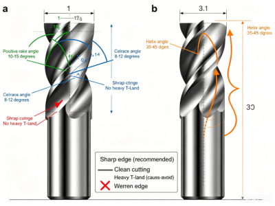
Wählen Sie einen Scharfen, Schneidkante mit positivem Spanwinkel, polierten Spannuten und genügend Freiraum, um Reibung zu vermeiden. Aluminiumspezifische Werkzeuge verwenden üblicherweise eine hohe Spirale und einen großen polierten Spanraum. Eine starke Kantenvorbereitung kann die Schnittkraft erhöhen und die Materialhaftung bei 6061-T6 fördern, während eine zu fragile Kante bei einem unterbrochenen oder instabilen Schnitt abplatzen kann. Die Werkzeuggeometrie sollte zur Operation passen, nicht nur der Name der Legierung.
Beschichtungsauswahl
Poliertes, unbeschichtetes Hartmetall, ZrN, und reibungsarme, aluminiumspezifische DLC-Beschichtungen sind gängige Wahl. PKD kann in einer stabilen Produktion wirtschaftlich sein, wenn eine lange Kantenlebensdauer und eine gleichmäßige Oberflächengüte die Werkzeugkosten rechtfertigen. Lehnen Sie eine Beschichtung nicht allein aufgrund ihres Namens ab oder genehmigen Sie sie nicht: Beschichtungszusammensetzung, Oberflächenglätte, Kantenvorbereitung, und die vom Werkzeuglieferanten vorgesehene Materialgruppe spielen eine Rolle.
So berechnen Sie Drehzahl und Vorschub
Kernformeln
Spindelgeschwindigkeit (U/min) = (Schnittgeschwindigkeit Vc x 1000) / (pi x Werkzeugdurchmesser D)
Tischfutter (mm/min) = Drehzahl x Zähnezahl z x Vorschub pro Zahn fz
Für einen 10 mm, Dreischneidiger Schaftfräser bei Vc = 400 m/min und fz = 0.06 mm/Zahn, Die berechnete Spindeldrehzahl beträgt ca 12,700 Die Drehzahl und der Tischvorschub betragen ca 2,290 mm/min. Wenn die Spindel begrenzt ist 10,000 U/min, Behalten Sie die vorgesehene Spanlast bei, indem Sie in der Nähe beginnen 1,800 mm/min, anstatt den ursprünglichen Vorschub beizubehalten und das Werkzeug reiben zu lassen.
Werkzeugdurchmesser | Drehzahl bei Vc 250 m/min | Drehzahl bei Vc 400 m/min | Drehzahl bei Vc 600 m/min |
3 mm | 26,500 | 42,400 | 63,700 |
6 mm | 13,300 | 21,200 | 31,800 |
10 mm | 8,000 | 12,700 | 19,100 |
16 mm | 5,000 | 8,000 | 11,900 |
20 mm | 4,000 | 6,400 | 9,500 |
Gerundete Berechnungen. Bestätigen Sie die maximale Drehzahl des Schneidgeräts, Inhaberbewertung, Spindelleistung, und Maschinengrenzen vor der Verwendung.
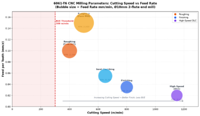
Die Chiplast ist nicht die ganze Geschichte
Der Vorschub pro Zahn ist eine Ausgangsgröße, Keine vollständige Beschreibung des Schnitts. Eine radiale Spanverdünnung kann die tatsächliche Spandicke bei geringem radialem Eingriff verringern, während der Werkzeugschlag dazu führen kann, dass eine Nut die meiste Last trägt. Eintrittsbewegungen, Ecken, stürzt, Rampen, und Änderungen im Eingriff erfordern möglicherweise eine separate Vorschubsteuerung. CAM-Simulation und Werkzeugwegglättung sind besonders nützlich bei tiefen Taschen und dünnwandigen Arbeiten.
Fräsgeschwindigkeiten und Vorschübe
Die folgenden Bereiche sind für scharfe Hartmetallwerkzeuge in einer starren CNC-Aufstellung gedacht. Beginnen Sie am unteren Ende, wenn das Werkzeug klein ist, Der Überhang ist lang, Engagement ist schwer, Die Spanabfuhr ist eingeschränkt, oder die Vorrichtung ist flexibel. Höhere Werte erfordern geeignete Werkzeuge, Gleichgewicht, Spindelfähigkeit, und Prozessbeweise.
Betrieb | Schnittgeschwindigkeit Vc (m/min) | Vorschub pro Zahn fz (mm/Zahn) | Beginn der Verlobung |
Schlitzung über die gesamte Breite | 200-350 | 0.03-0.08 | ap 0.3-1.0 x D; ae 1.0 x D |
Seitenfräsen / Schruppen | 250-500 | 0.04-0.12 | ap 0.5-1.5 x D; ae 0.2-0.6 x D |
Adaptives Schruppen | 300-600 | 0.04-0.15 | ap 1.0-2.0 x D; ae 0.08-0.25 x D |
Halbfertigbearbeitung | 350-700 | 0.03-0.08 | 0.2-0.5 mm Lager; ae 0.1-0.3 x D |
Abschluss | 400-1000 | 0.02-0.06 | 0.05-0.30 mm Lager; ae 0.05-0.2 x D |
Startbereiche nur zur Planung. D = Fräserdurchmesser. Lieferantendaten und Testschnitte steuern den freigegebenen Prozess.
Schruppstrategie
Mit konstantem Eingriff oder adaptiven Werkzeugwegen kann eine stabilere Fräserlast aufrechterhalten werden als beim herkömmlichen Taschenfräsen, insbesondere an Innenecken. Achten Sie auf eine ausreichende axiale Tiefe, um die nutzbare Nutlänge auszunutzen, Halten Sie jedoch den radialen Eingriff innerhalb der Kapazität von Werkzeug und Spindel. Ein Schlitzfräsvorgang ist bei gleicher Geschwindigkeit und gleichem Vorschub ein viel schwererer Schnitt als ein Seitenfräsdurchgang, daher sollten die beiden Parameter nicht automatisch gemeinsam nutzen.
Finishing-Strategie
Lassen Sie eine gleichmäßige Materialmenge für die Endbearbeitung übrig und verwenden Sie das kürzeste praktische Werkzeug. Ein Aufräumvorgang kann eine Wand nicht korrigieren, die bereits während des Schruppens aus ihrer Position verschoben wurde. Für sichtbare Flächen, Halten Sie die Fräsermarkierungen konsistent und entscheiden Sie, ob das Teil so bleibt, wie es bearbeitet wurde, oder ob es eloxiert wird, Perlenstrahlen, oder ein anderes Finish. Der 6061-Eloxierungsführung aus T6-Aluminium erklärt, wie die Textur bearbeitet wird, Schichtdicke, Maskierung, und Aussehensanforderungen wirken sich auf das endgültige Teil aus. JADE-CNC überprüft diesen Übergang durch seine CNC-Fräsdienstleistungen und Finishing-Unterstützung.
Bohrparameter
Bohrerdurchmesser | Schnittgeschwindigkeit (m/min) | Füttern (mm/U) | Prozesshinweis |
Unten 3 mm | 80-150 | 0.02-0.06 | Rundlauf und Spanansammlung dominieren; Verwenden Sie bei Bedarf kurze Stöße |
3-5 mm | 100-180 | 0.05-0.10 | Nur anbohren, wenn die Geometrie oder das Bohrerdesign dies erfordern |
5-10 mm | 120-250 | 0.08-0.20 | Verwenden Sie Kühlmittel oder Luft, um ein Nachschneiden der Späne zu verhindern |
10-20 mm | 150-300 | 0.15-0.30 | Überprüfen Sie die Maschinenleistung und die Fähigkeit zur Durchkühlung |
Über 20 mm | 150-300 | 0.20-0.40 | Pilot, indexierbar, oder Spiralinterpolation kann stabiler sein |
Die Bereiche setzen einen geeigneten Hartmetall- oder polierten HSS-Bohrer voraus. Befolgen Sie die durchmesserspezifischen Daten des Bohrerherstellers, sofern verfügbar.
Tiefe Löcher
Die Lochtiefe verändert den Prozess. Mit zunehmendem Verhältnis von Tiefe zu Durchmesser, Die Späne können weiter wandern und das Kühlmittel hat weniger Zugang zur Schneidkante. Für anspruchsvolle tiefe Bohrungen werden Bohrer mit Innenkühlung bevorzugt. Einige Werkzeuge und Maschinen können durch Picken hilfreich sein, Zu kurze Schnitte verlängern jedoch die Zykluszeit und können zum Abrieb oder Nachschneiden von Spänen führen. Verwenden Sie den vom Bohrerhersteller empfohlenen Zyklus und halten Sie den Nutweg frei.
Lochgenauigkeit
Durch Bohren allein kann ein enger Durchmesser möglicherweise nicht erreicht werden, Rundheit, Geradheit, oder Positionsanforderung. Ein praktischer Weg wäre das Bohren mit Untermaß, dann Bohren oder Reiben mit gleichmäßigem Aufmaß. Spotting ist nützlich, wenn die Eintrittsfläche, Standortanforderung, oder die Bohrkonstruktion erfordert es, Ein falscher Spitzenwinkel kann jedoch die Außenecken eines modernen Hartmetallbohrers beschädigen.
Gewindeschneiden und Gewindefräsen
Grober Faden | Tonhöhe / synchronisierter Feed (mm/U) | Typische Gewindeschneidgeschwindigkeit (m/min) | Hinweis zum Pilotloch |
M3 x 0.5 | 0.50 | 8-20 | Bestätigen Sie den Fadenanteil und tippen Sie auf die Lieferantentabelle |
M4 x 0.7 | 0.70 | 8-20 | Verwenden Sie nach Möglichkeit eine ausreichende Tiefe über das gesamte Gewinde hinaus |
M5 x 0.8 | 0.80 | 10-25 | Verwenden Sie polierte Nuten und geeignetes Schmiermittel |
M6 x 1.0 | 1.00 | 10-25 | Der starre Gewindebohrvorschub entspricht der Gewindesteigung |
M8 x 1.25 | 1.25 | 10-30 | Bei tiefen Sacklöchern die Geschwindigkeit reduzieren |
M10 x 1.5 | 1.50 | 10-30 | Entfernen Sie die Späne, bevor Sie einen Gewindebohrer umdrehen |
M12 x 1.75 | 1.75 | 10-30 | Drehmoment prüfen, Verlobungslänge, und Kühlmittelzugang |
Der synchronisierte Vorschub für starres Gewindeschneiden entspricht der Gewindesteigung. Die Schnittgeschwindigkeit variiert je nach Gewindebohrerdesign, Schmierung, Lochtiefe, und Maschinensynchronisation.
Wasserhähne schneiden, Formhähne, und Gewindemühlen
Geschnittene Gewindebohrer erzeugen Späne und benötigen einen Abführweg. Formgewindebohrer verdrängen Material ohne Späne, erfordern jedoch einen anderen Führungsdurchmesser und eine geeignete Duktilität, Drehmoment, und Schmierung. Gewindefräser bieten Durchmesserkontrolle, geringes Umkehrdrehmoment, und ein sichererer Fehlermodus bei wertvollen Teilen, obwohl sie Interpolation und normalerweise mehr Zykluszeit erfordern. Wählen Sie die Methode aus der Fadengröße, Tiefe, Klasse, Menge, Maschinenfähigkeit, und Inspektionsplan.
Eine generische Pilotlochformel ist kein Ersatz für die Tabelle des ausgewählten Gewindebohrers. Geben Sie das Thread-System und die Klasse an, Bestätigen Sie den gewünschten Prozentsatz des Engagements, und messen Sie das fertige Gewinde mit dem vereinbarten Stopfen oder der Funktionslehre.
Drehparameter
Betrieb | Schnittgeschwindigkeit (m/min) | Füttern (mm/U) | Schnitttiefe (mm) |
Grobes Drehen | 250-600 | 0.15-0.40 | 1.0-4.0 |
Fertigdrehen | 400-1000 | 0.05-0.15 | 0.10-0.50 |
Einstechen / Abschied | 150-350 | 0.04-0.15 | Abhängig von der Werkzeugbreite |
Einpunktgewindeschneiden | 50-200 | Gewindesteigung | Mehrere kontrollierte Pässe |
Verwenden Sie eine polierte Wendeschneidplatte mit positivem Spanwinkel, die für Nichteisenmaterialien geeignet ist. Passen Sie die Wendeplattengeometrie an, Arbeitsdurchmesser, Steifigkeit, und Spankontrolle.
Beim Drehen, Die Oberflächengeschwindigkeit ändert sich mit dem Durchmesser, Daher kann die Steuerung der konstanten Oberflächengeschwindigkeit die Konsistenz innerhalb der Spindelgrenze verbessern. Verwenden Sie eine Klemme mit maximaler Drehzahl, insbesondere in der Nähe der Mittellinie. Lange Späne können die Oberfläche beschädigen oder ein Sicherheitsrisiko darstellen; Wählen Sie eine Wendeschneidplattengeometrie und einen Vorschub, die beherrschbare Späne erzeugen, und gegebenenfalls gerichtetes Kühlmittel verwenden.
Kühlung, Schmierung, und Späneabfuhr
Verfahren | Wo es gut funktioniert | Hauptvorteil | Haupteinschränkung |
Kühlmittel überfluten | Allgemeines Schruppen, Bohren, und spanintensive Arbeiten | Kühlung, Schmierung, und Spänetransport | Konzentration, Wartung, und die Sauberkeit der Teile muss kontrolliert werden |
Kühlmittel durch das Werkzeug | Tiefbohren und schwierige Spanabfuhr | Fördert Späne aus der Schneidzone | Erfordert kompatible Werkzeuge, Inhaber, und Druck |
MQL | Leichtes Fräsen, klopfen, und sauberes Arbeiten | Gute Grenzschmierung bei wenig Flüssigkeit | Begrenzte Massenkühlung für den Abtrag schwerer Materialien |
Luftstoß | Abschluss, dünne Wände, und Trockenprozesse | Hält Späne fern, ohne dass Flüssigkeiten verunreinigt werden | Bietet wenig Schmierung und muss sicher aufbewahrt werden |
Luft plus MMS | Taschen und Fertigfräsen | Kombiniert Spänetransport mit Schmierung | Nebelabscheidung und gleichmäßige Abgabe sind wichtig |
Das beste System ist das, das die Schneidkante erreicht und die Späne zuverlässig abführt. Ein großes Kühlmittelvolumen, das von einer tiefen Tasche weggerichtet wird, kann weniger effektiv sein als ein gerichteter Luft- und Schmiermittelstrom. Halten Sie die Konzentration und Sauberkeit des Kühlmittels stabil, denn eine inkonsistente Schmierung kann das BUE-Verhalten verändern und Aluminiumoberflächen vor der Endbearbeitung verfärben.
Befestigung und Dünnwandkontrolle
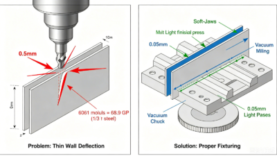
Dünne 6061-T6-Wände können sich unter Klemmlast bewegen, Schnittkraft, Eigenspannung, und Hitze. Die Vorrichtung sollte das Teil wiederholbar lokalisieren, ohne es in eine künstliche Form zu zwingen, die nach der Freigabe zurückspringt. Der 6061-T6-CNC-Bearbeitungs-DFM-Richtlinien Geben Sie zusätzliche Regeln für Wände an, Taschen, Radien, Löcher, Threads, und Toleranzzuordnung. JADE-CNCs Überprüfung der kundenspezifischen CNC-Bearbeitung berücksichtigt den Lagerzustand, Datumswahl, Zugang, Unterstützung, und Bearbeitungsreihenfolge zusammen.
- Verwenden Sie breit, Wiederholbare Kontaktbereiche und wenden Sie nur die Klemmkraft an, die für die Stabilität erforderlich ist.
- Aufrauen der gegnerischen Seiten in einer ausgewogenen Reihenfolge, wenn große Materialmengen entfernt werden.
- Lassen Sie ein gleichmäßiges Finish-Material übrig und lassen Sie das Teil vor dem letzten Arbeitsgang stabilisieren.
- Stützen Sie dünne Wände mit weichen Backen, Vorrichtungen, Opfermaterial, oder Vakuum-Werkstückhalterung, falls erforderlich.
- Radialen Eingriff reduzieren, Werkzeugüberstand verkürzen, und vermeiden Sie plötzliche Richtungsänderungen in der Nähe flexibler Merkmale.
- Definieren Sie, ob kritische Abmessungen im festgehaltenen Zustand oder im freien Zustand geprüft werden.
Behebung häufiger Bearbeitungsprobleme
Problem | Wahrscheinliche Ursachen | Praktische Kontrollen |
Aufbaukante | Stumpfe oder ungeeignete Kante, niedrige effektive Geschwindigkeit, Reiben, schlechte Schmierung, Spannachschneiden | Untersuchen Sie die Kante, Bestätigen Sie die Chipladung, Verbesserung der Schmierung und Evakuierung, dann Geschwindigkeit anpassen |
Schlechte Oberflächenbeschaffenheit | Auslaufen, Geschwätz, BOGEN, Werkzeugverschleiß, überschüssiges Futter, instabiler Bestand | Halter und Spindel prüfen, Überhang verkürzen, Stabilisieren Sie das Teil, und ein gleichmäßiges Finishmaterial hinterlassen |
Starke Grate | Stumpfer Rand, schwache Ausstiegsunterstützung, ungeeigneter Werkzeugweg, überschüssiges Futter beim Durchbruch | Verwenden Sie ein scharfes Werkzeug, den Ausstieg unterstützen, Schnittrichtung ändern, und wenden Sie einen kontrollierten Kantenbruch an |
Spanschweißen | Heiß nachgeschnittene Späne, begrenzter Flötenraum, schlechte Kühlmittelzufuhr | Verwenden Sie ein Aluminium-spezifisches Werkzeug, Platz für den Chip hinzufügen, und den Luft- oder Kühlmittelzugang verbessern |
Dünnwandige Bewegung | Klemmverzerrung, Eigenspannung, übermäßige Schnittkraft, Hitze | Abtragen des Restmaterials, Engagement reduzieren, Stützen Sie die Wand, und fertig, nachdem sich das Teil stabilisiert hat |
Lochgrößendrift | Bohrerauslauf, Hitze, Aufbaukante, instabiler Eintrag, abgenutzte Reibahle | Prüfen Sie den Rundlauf, Verwenden Sie einen kontrollierten Eintrag, Lassen Sie ein gleichmäßiges Reibmaterial zurück, und Temperatur überprüfen |
Wasserhahnfehler | Falscher Pilot, Chipverpackung, Fehlausrichtung, hohes Drehmoment, unzureichendes Schmiermittel | Überprüfen Sie die Größe des Piloten und die Gewindetiefe, Verwenden Sie eine starre Synchronisierung, klare Chips, und wählen Sie den richtigen Hahnstil aus |
Ändern Sie während der Fehlerbehebung jeweils eine Variable und notieren Sie das Ergebnis. Spindeldrehzahl erhöhen, Reduzierung des Futters, Kühlmittel wechseln, und das gleichzeitige Ersetzen des Werkzeugs kann das Teil verbessern, aber es offenbart nicht die Ursache. Ein kurzer kontrollierter Versuch lässt sich leichter wiederholen und in die Produktion übertragen.
Enge Toleranzen erreichen
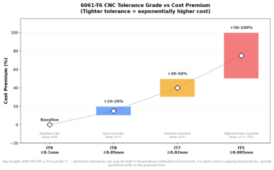
Eine Toleranz ist nur dann glaubwürdig, wenn sie an die Merkmalsgröße gebunden ist, Geometrie, Datumsstruktur, materieller Zustand, Temperatur, Oberflächenbeschaffenheit, und Messunsicherheit. Eine pauschale Funktion wie z +/-0.01 mm sagt wenig über eine lange dünne Wand aus, eine kleine Bohrung, oder ein großer flacher Teller. Stellen Sie strenge Anforderungen nur an Merkmale, die sich auf Passform oder Funktion auswirken, und definieren Sie die Prüfmethode, bevor mit der Bearbeitung begonnen wird.
Erfordernis | Prozessplanung | Inspektionsplanung |
Allgemeine Abmessungen | Verwenden Sie eine dokumentierte Werkstatt- oder Zeichnungstoleranz | Für unkritische Merkmale können kalibrierte Handwerkzeuge ausreichend sein |
Bohrungen und Schächte verschließen | Langweilig, Ries, oder Fertigdrehen mit kontrolliertem Material und kontrollierter Temperatur | Verwenden Sie geeignete Bohrlehren, Luftmessgeräte, oder ein KMG, je nach Größe und Unsicherheit |
Position und Profil | Verwenden Sie stabile Bezugspunkte und minimieren Sie Setup-Änderungen | Definieren Sie die Datumssimulation und bewerten Sie den angegebenen GD&T-Anforderung |
Ebenheit und Parallelität | Materialabtrag ausgleichen und Spannverzug vermeiden | Unterstützen Sie den Teil konsequent und berücksichtigen Sie die Anforderungen des Freistaats |
Oberflächenstruktur | Geben Sie den prozessrelevanten Parameter und die Messrichtung an | Vereinbaren Sie die Geräteeinstellungen, Standort, Abschaltung, und Akzeptanzregel |
Dünne Wände | Verwenden Sie bei Bedarf eine Endbearbeitung mit geringem Kraftaufwand und schrittweises Lösen | Messen Sie im definierten eingespannten oder freien Zustand |
Für Größentoleranzen und Passungen, ISO 286-1:2010 bildet die Grundlage des ISO-Codesystems. Geometrische Kontrollen wie Ebenheit, Position, und Profil werden durch definiert ISO 1101:2017. Angaben zur Oberflächenbeschaffenheit sollten dem geltenden Zeichnungssystem folgen; ISO 21920-1:2021 behandelt Angaben zur Profilmethode in der technischen Produktdokumentation.
Temperatur und Messung
Aluminium dehnt sich um ca 23 Zu 24 ähm pro Meter pro Sie C. Auf einem 100 mm-Funktion, A 10 Ein Temperaturunterschied von etwa 100 °C kann die Größe um etwa 100 % ändern 0.023 Zu 0.024 mm. Lassen Sie das Teil und die Lehre einen stabilen Zustand erreichen, bekannte Temperatur vor der endgültigen Messung, und verwenden Sie eine Prüfmethode, deren Unsicherheit klein genug für die angegebene Toleranz ist. JADE-CNC kann diese Anforderungen mit seinen in Einklang bringen CNC-Inspektionsdienste.
Workflow zur Parametervalidierung
- Legierung bestätigen, Temperament, Lagerform, Feature-Geometrie, Toleranz, und Finish-Anforderungen.
- Wählen Sie ein aluminiumspezifisches Werkzeug aus und holen Sie sich die Ausgangsdaten des Lieferanten ein.
- Berechnen Sie Drehzahl und Vorschub, dann wenden Sie die Spindel an, Leistung, Halter, und Spanngrenzen.
- Programmeintrag, Ecken, Engagement verändert sich, Spanabfuhr, und die maximale Drehzahl gezielt einsparen.
- Führen Sie ein kontrolliertes Erstartikel- und Aufzeichnungstool aus, Halter, Überhang, Kühlmittel, Geschwindigkeiten, füttert, und Offsets.
- Überprüfen Sie kritische Abmessungen, Threads, Grate, und Oberflächenzustand mit der vereinbarten Methode.
- Passen Sie jeweils eine Variable an, den bewährten Prozess freigeben, und überwachen Sie die Werkzeugstandzeit in der Produktion.
Die Parameteroptimierung sollte erst beginnen, nachdem die Fertigungsroute festgelegt ist. Für großvolumige Teile, die gegossen statt aus Schmiedematerial geschnitten werden können, Die 6061-Vergleich zwischen T6 und ADC12 Aluminium erklärt die Unterschiede bei den Werkzeuginvestitionen, Stückkosten, Eigenschaften, Toleranzen, und Abschluss.
Wie JADE-CNC die 6061-T6-Bearbeitung angeht
JADE-CNC bearbeitet kundenspezifische 6061-T6-Komponenten von Prototypen bis hin zur Wiederholungsproduktion. Die Parameterauswahl beginnt mit dem Teil und nicht mit einem generischen Diagramm: Das Team überprüft den Toolzugriff, Wandstabilität, Toleranzzonen, Oberflächenanforderungen, Inspektionspunkte, Menge, und das geplante Ende, bevor Sie den Prozessweg bestätigen.
- 3-Achse, 4-Achse, und 5-Achsen-Fräsrouten, die rund um den Funktionszugriff und die Einrichtungskontrolle ausgewählt wurden
- CNC-Drehen, Bohren, klopfen, langweilig, und Gewindefräsunterstützung
- Überprüfung der Vorrichtungs- und Bearbeitungsreihenfolge für dünne Wände, Teller, Gehäuse, und tiefe Taschen
- Parameterversuche und Erstmusterprüfungen für kritische oder wiederkehrende Merkmale
- Oberflächenvorbereitung und Koordination der Oberflächenveredelungfür eloxierte oder kosmetische Teile
- Dimensional, Faden, Oberfläche, und CMM-Inspektion gemäß dem vereinbarten Umfang
Für Prototypen oder Wiederholungsserien, Senden Sie das 3D-Modell, 2D-Zeichnung, materieller Zustand, Menge, beenden, und Inspektionsanforderungen an Fordern Sie eine JADE-CNC-Bearbeitungsbewertung an.
Häufig gestellte Fragen
Häufige Fragen zu Parametern und Prozessen
Welche Schnittgeschwindigkeit sollte ich für 6061-T6-Aluminium verwenden??
Zum Hartmetallfräsen, 200-600 m/min ist ein praktischer Planungsbereich für viele Schruppoperationen, während stabile Finishing-Prozesse möglicherweise höher laufen. Der richtige Wert hängt vom genauen Fräser ab, Beschichtung, Durchmesser, Engagement, Spindel, Halter, Kühlmittel, und Daten des Werkzeuglieferanten.
Welcher Vorschub pro Zahn ist für einen Schaftfräser 6061-T6 geeignet??
Viele Hartmetallfräsanwendungen beginnen dazwischen 0.02 Und 0.15 mm/Zahn. Kleine Werkzeuge, Fertigschnitte, und instabile Merkmale nutzen den unteren Teil des Bereichs; Bei größeren starren Schruppwerkzeugen kann der obere Teil verwendet werden. Passen Sie Unrundheit und radiale Spanverdünnung an.
Welche Schaftfräserbeschichtung eignet sich am besten für 6061-T6??
Poliertes, unbeschichtetes Hartmetall, ZrN, und aluminiumspezifisches DLC sind gängige Optionen. Die beste Option hängt von der Werkzeuggeometrie ab, Kantenpolitur, Anwendung, Menge, Kühlmittel, und Kosten. Nutzen Sie die Nichteisenempfehlung des Lieferanten, anstatt nur anhand des Beschichtungsnamens auszuwählen.
Warum verschweißt Aluminium mit der Schneide??
Aufbauschnittkanten resultieren in der Regel aus einer Kombination von Materialhaftung, eine ungeeignete oder stumpfe Kante, Reiben, Hitze, eingeschränkte Schmierung, und Spannachschneiden. Überprüfen Sie zunächst das Werkzeug, Überprüfen Sie dann die Chiplast, Schnittgeschwindigkeit, Engagement, Kühlmittelzufuhr, und Evakuierung.
Kann 6061-T6-Teile aufnehmen +/-0.01 mm?
Einige Funktionen können, Die Machbarkeit hängt jedoch von der Nenngröße ab, Geometrie, Wandstärke, Lagerzustand, Temperatur, Maschinenstabilität, Befestigung, Abschluss, und Inspektionsunsicherheit. Bevor dieser Wert als Produktionsfähigkeit behandelt wird, ist eine Zeichnungsprüfung erforderlich.
Ist Flutkühlmittel für Aluminium immer besser??
NEIN. Flutkühlmittel sind für viele Schrupp- und Bohrvorgänge wirksam, während MMS oder Luft für leichte Endbearbeitung und saubere Prozesse geeignet sein können. Schnittgerechte Lieferung und zuverlässige Spanabfuhr sind wichtiger als die Bezeichnung der Kühlmethode.
Abschluss
Die erfolgreiche 6061-T6-Bearbeitung basiert auf einem scharfen, aluminiumspezifischen Werkzeug, eine sinnvolle Spanlast, stabiles Engagement, Zuverlässige Spanabfuhr, kontrollierte Werkstückspannung, und Inspektion, die der Zeichnung entspricht. Geschwindigkeits- und Vorschubtabellen sind hilfreich, um einen Startpunkt abzuschätzen, Sie können jedoch werkzeugspezifische Daten und einen geprüften Erstartikel nicht ersetzen.
Dokumentieren Sie das freigegebene Werkzeug, Halter, Überhang, Kühlmittelmethode, U/min, füttern, Engagement, Werkzeugweg, Offsets, und Inspektionsergebnisse. Dieser Rekord macht aus einem guten Testschnitt einen wiederholbaren Produktionsprozess.
Verwandte 6061-T6-Artikel
- 6061-Vollständiger Leitfaden zur T6-Aluminium-CNC-Bearbeitung
- 6061-T6 vs. 7075-T6 Aluminium: Stärke, Kosten & Bearbeitbarkeit
- 6061-T6 Aluminium eloxiert: Typen, Farben, Dicke & Designregeln
- 6061-T6 CNC-Bearbeitungsparameter: Geschwindigkeiten, Feeds, Werkzeuge & Prozesskontrolle
- 6061-T6 vs. ADC12 Aluminium: CNC-Bearbeitung oder Druckguss?
- 6061-T6 CNC-Bearbeitungs-DFM-Richtlinien: Designregeln & Checkliste
- 6061-Eigenschaften von T6-Aluminium: Mechanisch, Thermal & Chemische Daten

Leo Liang, Gründer Bester Partner mit R&D
JADE-CNCs Gründer LEO, der über zwei Jahrzehnte Branchenexpertise mitbringt, Leo begann seine Karriere als Lehrling und erprobte seine Fähigkeiten in der Oberflächenbehandlung und CNC-Bearbeitung.
Hallo, Du hast einen unglaublichen Job gemacht. Ich werde es auf jeden Fall mögen und
Persönlich meinen Freunden empfehlen. Ich bin sicher
Sie werden von dieser Website profitieren.
Ich würde mich freuen, wenn der Artikel Ihnen weiterhelfen kann, Danke!