



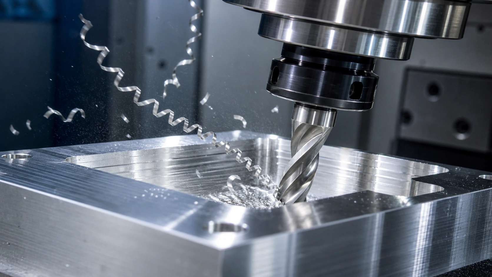
Plages de départ pratiques pour le fraisage, forage, tapotement, et tournage de l'aluminium 6061-T6, avec des conseils sur l'outillage, contrôle des copeaux, parois minces, tolérances, et validation des processus.
Introduction
6061-Le T6 est indulgent par rapport à de nombreux métaux techniques, mais cela récompense toujours un processus discipliné. Un outil tranchant peut enlever rapidement de la matière et laisser une finition propre. Le même alliage peut également produire des bords rapportés, copeaux soudés, bavures, bavarder, ou dérive dimensionnelle lorsque la fraise, charge de copeaux, fiançailles, refroidissement, et le luminaire ne fonctionnent pas ensemble.
Ce guide donne des plages de départ pratiques plutôt que des recettes universelles. Les paramètres finaux dépendent du diamètre et de la géométrie de l'outil, puissance de broche, régime maximum, faux-rond du support, porte-à-faux de l'outil, engagement radial et axial, livraison de liquide de refroidissement, porte-pièce, profondeur des fonctionnalités, et la surface ou la tolérance requise. Utiliser les données de coupe du fabricant de l'outil comme référence principale, puis confirmez le processus avec des coupes d'essai contrôlées.
Pour un aperçu plus large des matériaux et de la conception, voir JADE-CNC 6061-Guide d'usinage CNC en aluminium T6. Les sections ci-dessous se concentrent sur la sélection des paramètres et le contrôle des processus en atelier..
Pourquoi le 6061-T6 fonctionne bien
6061-T6 combine une dureté modérée, force utile, bonne conductivité thermique, et des forces de coupe relativement faibles. Il forme généralement des copeaux gérables avec des, outils à râteau positif. Ces caractéristiques permettent des taux d'enlèvement de matière élevés et une bonne qualité de surface sans le comportement d'écrouissage sévère associé à certains aciers inoxydables ou alliages de nickel..
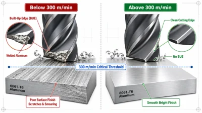
Ses avantages s'accompagnent de trois risques liés au processus. L'aluminium peut adhérer au tranchant, des fonctionnalités profondes peuvent piéger les puces, et les sections minces peuvent fléchir car le module élastique est bien inférieur à celui de l'acier. La dilatation thermique est également importante lorsque les dimensions sont mesurées à quelques centièmes ou millièmes de millimètre.. Un bon usinage dépend donc autant de l'évacuation des copeaux, porte-pièce, et la température comme c'est le cas pour la vitesse de broche.
La force sous-jacente, module, conductivité, et les données d'expansion sont couvertes dans le 6061-Guide des propriétés de l'aluminium T6. Si une pièce nécessite une résistance nettement plus élevée, comparer les compromis d'usinage et de coûts dans 6061-T6 contre aluminium 7075-T6 avant de modifier le processus de découpe.
Sélection d'outils pour 6061-T6
Opération | Outil préféré | Géométrie ou revêtement | Notes de sélection |
Fraisage général | Fraise en carbure monobloc | Poli sans revêtement, ZrN, ou DLC spécifique à l'aluminium | Utilisez un bord tranchant et suffisamment d'espace pour les cannelures pour l'évacuation des copeaux. |
Poches et fentes profondes | 2- ou fraise en carbure à 3 cannelures | Hélice haute avec cannelures polies | Moins de cannelures offrent plus d'espace pour les puces |
Finition | 3-flûte en carbure ou PCD lorsque cela est justifié | Pointu, bord à faible friction | Choisissez un faible faux-rond et un support rigide avant d'augmenter la vitesse |
Forage | Foret HSS carbure ou poli | Géométrie en aluminium; arrosage traversant pour trous profonds | La géométrie des pointes et l'évacuation des copeaux sont d'autant plus importantes à mesure que la profondeur augmente |
Tapotement | Taraud à goujure spirale ou forme spécifique à l'aluminium | Flûtes polies ou traitement de surface adapté | Sélectionnez le taraud et le trou pilote pour la classe de filetage et l'engagement. |
Tournant | Insert en carbure poli à râteau positif | Pointu, qualité non ferreuse | Utilisez une configuration stable et contrôlez les longs copeaux filandreux |
Alésage ou alésage de précision | Outil d'alésage ou alésoir en carbure | Arête vive et faux-rond minimal | Laisser une marge constante et vérifier à température contrôlée |
Nombre de flûtes de fraise en bout
Les fraises à deux cannelures offrent un espace généreux pour les copeaux et sont utiles pour les fentes étroites, poches profondes, et machines avec un débit d'air ou de liquide de refroidissement limité. Les fraises à trois cannelures offrent souvent un bon équilibre en matière de dégagement des copeaux, rigidité, et productivité pour le fraisage général de l'aluminium. Quatre cannelures ou plus peuvent bien fonctionner pour une finition légère ou des stratégies à grande vitesse lorsque les vallées de cannelures et le système d'évacuation peuvent suivre le volume des copeaux..
Géométrie de l'outil et état des bords
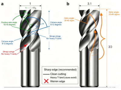
Choisissez un tranchant, bord de coupe à râteau positif avec cannelures polies et suffisamment d'espace pour éviter les frottements. Les outils spécifiques à l'aluminium utilisent généralement une hélice haute et un grand œsophage poli. Une préparation lourde des bords peut augmenter la force de coupe et favoriser l'adhérence du matériau sur le 6061-T6, tandis qu'un bord trop fragile peut s'écailler lors d'une coupe interrompue ou instable. La géométrie de l'outil doit correspondre à l'opération, pas seulement le nom de l'alliage.
Choix du revêtement
Carbure poli non revêtu, ZrN, et les revêtements DLC spécifiques à l'aluminium à faible friction sont des choix courants. Le PCD peut être économique dans une production stable où la longue durée de vie des arêtes et la finition constante justifient le coût de l'outil.. Ne rejetez pas ou n’approuvez pas un revêtement uniquement par son nom.: composition de revêtement, douceur de la surface, préparation des bords, et le groupe de matériaux prévu par le fournisseur d’outils sont tous importants.
Comment calculer le régime et le taux d'alimentation
Formules de base
Vitesse de broche (RPM) = (vitesse de coupe Vc x 1000) / (pi x diamètre de l'outil D)
Flux de table (mm/min) = RPM x nombre de dents z x avance par dent fz
Pour un 10 mm, fraise à trois dents à Vc = 400 m/min et fz = 0.06 mm/dent, la vitesse de broche calculée est d'environ 12,700 RPM et le flux de la table est d'environ 2,290 mm/min. Si la broche est limitée à 10,000 RPM, préserver la charge de copeaux prévue en commençant à proximité 1,800 mm/min plutôt que de conserver l'avance d'origine et de laisser l'outil frotter.
Diamètre de l'outil | RPM à Vc 250 m/min | RPM à Vc 400 m/min | RPM à Vc 600 m/min |
3 mm | 26,500 | 42,400 | 63,700 |
6 mm | 13,300 | 21,200 | 31,800 |
10 mm | 8,000 | 12,700 | 19,100 |
16 mm | 5,000 | 8,000 | 11,900 |
20 mm | 4,000 | 6,400 | 9,500 |
Calculs arrondis. Confirmez le régime maximum du coupeur, qualification du titulaire, puissance de broche, et limites de la machine avant utilisation.
La charge des puces n’est pas toute l’histoire
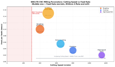
L'avance par dent est une variable de départ, pas une description complète de la coupe. L'amincissement radial des copeaux peut réduire l'épaisseur réelle des copeaux en cas d'engagement radial faible, tandis que le faux-rond de l'outil peut faire qu'une flûte supporte la majeure partie de la charge. Mouvements d'entrée, coins, plonge, rampes, et les changements d'engagement peuvent nécessiter un contrôle de flux séparé. La simulation CAM et le lissage des parcours d'outils sont particulièrement utiles dans les poches profondes et les travaux à parois fines..
Vitesses et avances de fraisage
Les gammes suivantes sont destinées aux outils tranchants en carbure dans une configuration CNC rigide. Commencez près de l’extrémité inférieure lorsque l’outil est petit, le surplomb est long, les fiançailles sont lourdes, l'évacuation des copeaux est limitée, ou le luminaire est flexible. Des valeurs plus élevées nécessitent un outillage adapté, équilibre, capacité de la broche, et traiter les preuves.
Opération | Vitesse de coupe Vc (m/min) | Avance par dent fz (mm/dent) | Début des fiançailles |
Fentes pleine largeur | 200-350 | 0.03-0.08 | ap 0.3-1.0 xD; ae 1.0 xD |
Fraisage latéral / ébauche | 250-500 | 0.04-0.12 | ap 0.5-1.5 xD; ae 0.2-0.6 xD |
Ebauche adaptative | 300-600 | 0.04-0.15 | ap 1.0-2.0 xD; ae 0.08-0.25 xD |
Semi-finition | 350-700 | 0.03-0.08 | 0.2-0.5 mm de matière; ae 0.1-0.3 xD |
Finition | 400-1000 | 0.02-0.06 | 0.05-0.30 mm de matière; ae 0.05-0.2 xD |
Plages de départ pour la planification uniquement. D = diamètre de la fraise. Les données des fournisseurs et les coupes de test contrôlent le processus validé.
Stratégie d'ébauche
Les parcours d'outils à engagement constant ou adaptatifs peuvent maintenir une charge de coupe plus stable que l'usinage de poches conventionnel., en particulier dans les coins internes. Utiliser suffisamment de profondeur axiale pour engager la longueur utile de la cannelure, mais gardez l’engagement radial dans les limites de la capacité de l’outil et de la broche. Une rainure est une coupe beaucoup plus lourde qu'une passe de fraisage latéral à la même vitesse et avance, donc les deux ne devraient pas partager automatiquement les paramètres.
Stratégie de finition
Laissez une quantité uniforme de matériau pour la finition et utilisez l'outil pratique le plus court. Une passe de nettoyage ne peut pas corriger un mur qui a déjà été déplacé lors de l'ébauche.. Pour les surfaces visibles, garder les marques de coupe cohérentes et décider si la pièce restera telle qu'usinée ou recevra une anodisation, microbillage, ou une autre finition. Le 6061-Guide d'anodisation en aluminium T6 explique comment la texture est usinée, épaisseur du revêtement, masquage, et les exigences d'apparence affectent la pièce finale. JADE-CNC revient sur cette transition à travers son Services de fraisage CNC et support de finition.
Paramètres de forage
Diamètre du foret | Vitesse de coupe (m/min) | Alimentation (mm/tour) | Note de processus |
Ci-dessous 3 mm | 80-150 | 0.02-0.06 | Le faux-rond et le conditionnement des copeaux dominent; utilisez de courts picotements si nécessaire |
3-5 mm | 100-180 | 0.05-0.10 | Repérer uniquement lorsque la géométrie ou la conception du foret l'exige |
5-10 mm | 120-250 | 0.08-0.20 | Utiliser du liquide de refroidissement ou de l'air pour éviter la recoupe des copeaux |
10-20 mm | 150-300 | 0.15-0.30 | Vérifier la puissance de la machine et la capacité du liquide de refroidissement |
Au-dessus de 20 mm | 150-300 | 0.20-0.40 | Pilote, indexable, ou l'interpolation hélicoïdale peut être plus stable |
Les gammes supposent un foret HSS en carbure ou poli approprié. Suivez les données spécifiques au diamètre du fabricant de forets lorsqu'elles sont disponibles.
Trous profonds
La profondeur du trou change le processus. À mesure que le rapport profondeur/diamètre augmente, les copeaux ont plus de chemin à parcourir et le liquide de refroidissement a moins accès au tranchant. Les forets à refroidissement direct sont préférés pour les trous profonds exigeants. Le picage peut aider certains outils et machines, mais des pics trop courts augmentent le temps de cycle et peuvent frotter ou recouper les copeaux. Utilisez le cycle recommandé par le fabricant de la perceuse et gardez le chemin de la flûte dégagé.
Précision du trou
Le perçage seul peut ne pas satisfaire un diamètre étroit, rondeur, rectitude, ou exigence du poste. Un itinéraire pratique peut inclure le forage sous-dimensionné, puis ennuyeux ou alésage avec une allocation constante. Le repérage est utile lorsque la surface d'entrée, exigence d'emplacement, ou la conception de la perceuse l'exige, mais un angle de point incorrect peut endommager les coins extérieurs d’un foret en carbure moderne.
Taraudage et fraisage de filetage
Fil grossier | Pas / flux synchronisé (mm/tour) | Vitesse de coupe typique (m/min) | Note sur le trou pilote |
M3x 0.5 | 0.50 | 8-20 | Confirmer le pourcentage de fil et le tableau des fournisseurs de tarauds |
M4x 0.7 | 0.70 | 8-20 | Utilisez une profondeur adéquate au-delà du filetage complet lorsque cela est possible |
M5x 0.8 | 0.80 | 10-25 | Utiliser des flûtes polies et un lubrifiant approprié |
M6x 1.0 | 1.00 | 10-25 | L'avance de taraudage rigide est égale au pas du filetage |
M8x 1.25 | 1.25 | 10-30 | Réduire la vitesse pour les trous borgnes profonds |
M10x 1.5 | 1.50 | 10-30 | Éliminer les copeaux avant d'inverser un taraud |
M12x 1.75 | 1.75 | 10-30 | Vérifier le couple, durée des fiançailles, et accès au liquide de refroidissement |
L'avance synchronisée pour le taraudage rigide est égale au pas du filetage. La vitesse de coupe varie selon la conception du taraud, lubrification, profondeur du trou, et synchronisation des machines.
Couper les tarauds, Robinets de formulaire, et moulins à fil
Les robinets coupés créent des copeaux et nécessitent un chemin d'évacuation. Les tarauds de forme déplacent le matériau sans copeaux mais nécessitent un diamètre pilote différent et une ductilité appropriée, couple, et lubrification. Les fraises à fileter offrent un contrôle du diamètre, faible couple d'inversion, et un mode de défaillance plus sûr sur les pièces de valeur, bien qu'ils nécessitent une interpolation et généralement plus de temps de cycle. Choisissez la méthode à partir de la taille du fil, profondeur, classe, quantité, capacité de la machine, et plan d'inspection.
Une formule générique de trou pilote ne remplace pas le tableau des tarauds sélectionnés.. Spécifiez le système de thread et la classe, confirmer le pourcentage d’engagement souhaité, et calibrer le filetage terminé avec le bouchon ou la jauge fonctionnelle convenue.
Paramètres de tournage
Opération | Vitesse de coupe (m/min) | Alimentation (mm/tour) | Profondeur de coupe (mm) |
Tournage grossier | 250-600 | 0.15-0.40 | 1.0-4.0 |
Terminer le tournage | 400-1000 | 0.05-0.15 | 0.10-0.50 |
Rainurage / séparation | 150-350 | 0.04-0.15 | Dépend de la largeur de l'outil |
Filetage monopoint | 50-200 | Pas de filetage | Plusieurs passes contrôlées |
Utiliser une plaquette polie à râteau positif destinée aux matériaux non ferreux. Ajuster à la géométrie de la plaquette, diamètre de travail, rigidité, et contrôle des copeaux.
En tournant, la vitesse de la surface change avec le diamètre, le contrôle de la vitesse de surface constante peut donc améliorer la cohérence dans les limites de la broche. Utilisez une pince à régime maximum, en particulier près de la ligne médiane. Les copeaux longs peuvent endommager la surface ou créer un risque pour la sécurité; sélectionner une géométrie de plaquette et une avance qui produisent des copeaux gérables, et utiliser du liquide de refroidissement dirigé le cas échéant.
Refroidissement, Lubrification, et évacuation des copeaux
Méthode | Où ça marche bien | Principal avantage | Principale limite |
Liquide de refroidissement inondé | Ebauche générale, forage, et travaux exigeants en copeaux | Refroidissement, lubrification, et transport de copeaux | Concentration, entretien, et la propreté des pièces doit être contrôlée |
Liquide de refroidissement traversant l'outil | Forage profond et évacuation des copeaux difficiles | Évacue les copeaux hors de la zone de coupe | Nécessite des outils compatibles, titulaires, et la pression |
MQL | Fraisage léger, tapotement, et un travail propre | Bonne lubrification des limites avec peu de liquide | Refroidissement en vrac limité pour l'enlèvement de matériaux lourds |
Souffle d'air | Finition, parois minces, et procédés secs | Éloigne les copeaux sans contamination liquide | Fournit peu de lubrification et doit être contenu en toute sécurité |
Air plus MQL | Poches et fraisage de finition | Combine le transport des copeaux avec la lubrification | La collecte du brouillard et une livraison constante sont importantes |
Le meilleur système est celui qui atteint le tranchant et élimine les copeaux de manière fiable. Un grand volume de liquide de refroidissement dirigé loin d'une poche profonde peut être moins efficace qu'un flux d'air et de lubrifiant dirigé.. Maintenir la concentration et la propreté du liquide de refroidissement stables, car une lubrification incohérente peut modifier le comportement du BUE et tacher les surfaces en aluminium avant la finition.
Contrôle des luminaires et des parois minces
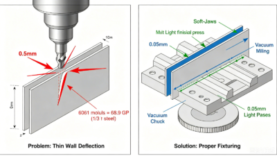
Les parois minces en 6061-T6 peuvent se déplacer sous la charge de serrage, force de coupe, contrainte résiduelle, et de la chaleur. Le dispositif doit localiser la pièce de manière répétée sans la forcer à prendre une forme artificielle qui reprendra sa forme après le relâchement.. Le 6061-Directives DFM pour l'usinage CNC T6 fournir des règles supplémentaires pour les murs, poches, rayons, trous, fils de discussion, et allocation de tolérance. JADE-CNC examen de l'usinage CNC personnalisé prend en compte l'état du stock, choix de référence, accéder, soutien, et séquence d'usinage ensemble.
- Utiliser large, zones de contact reproductibles et appliquer uniquement la force de serrage nécessaire à la stabilité.
- Ébaucher les côtés opposés dans une séquence équilibrée lorsque de grandes quantités de matière sont enlevées.
- Laisser un stock de finition uniforme et laisser la pièce se stabiliser avant la passe finale.
- Supporte les parois fines avec des mâchoires souples, luminaires, matériau sacrificiel, ou maintien sous vide, le cas échéant.
- Réduire l'engagement radial, raccourcir le porte-à-faux de l'outil, et évitez les changements de direction brusques à proximité d'éléments flexibles.
- Définir si les dimensions critiques sont inspectées en position retenue ou à l'état libre.
Dépannage des problèmes d'usinage courants
Problème | Causes probables | Vérifications pratiques |
Bord accumulé | Bord émoussé ou inadapté, faible vitesse effective, frottement, mauvaise lubrification, recoupe de copeaux | Inspecter le bord, confirmer le chargement des puces, améliorer la lubrification et l'évacuation, puis ajustez la vitesse |
Mauvaise finition de surface | S'épuiser, bavarder, ARC, usure des outils, excès de nourriture, stock instable | Porte-chèque et broche, raccourcir le porte-à-faux, stabiliser la pièce, et laisser un stock de finition uniforme |
Bavures lourdes | Bord terne, faible soutien à la sortie, parcours d'outil inapproprié, excès d'alimentation à la percée | Utilisez un outil pointu, soutenir la sortie, changer la direction de coupe, et appliquez une rupture de bord contrôlée |
Soudage des copeaux | Copeaux découpés à chaud, espace de flûte restreint, mauvais débit de liquide de refroidissement | Utiliser un outil spécifique à l'aluminium, ajouter de l'espace pour la puce, et améliorer l'accès à l'air ou au liquide de refroidissement |
Mouvement à paroi mince | Distorsion de serrage, contrainte résiduelle, force de coupe excessive, chaleur | Équilibrage de la matière, réduire l'engagement, soutenir le mur, et terminer une fois la pièce stabilisée |
Dérive de taille de trou | Faux-rond du forage, chaleur, bord bâti, entrée instable, alésoir usé | Vérifier le faux-rond, utiliser une entrée contrôlée, laisser un stock d'alésage constant, et vérifier la température |
Échec du robinet | Pilote incorrect, emballage des copeaux, désalignement, couple élevé, lubrifiant insuffisant | Vérifier la taille du pilote et la profondeur du filetage, utiliser une synchronisation rigide, chips claires, et sélectionnez le style de robinet correct |
Modifiez une variable à la fois pendant le dépannage et enregistrez le résultat. Augmentation de la vitesse de broche, réduire l'alimentation, changer le liquide de refroidissement, et le remplacement de l'outil simultanément peut améliorer la pièce, mais cela ne révèle pas la cause. Un essai contrôlé court est plus facile à répéter et à transférer en production.
Atteindre des tolérances strictes
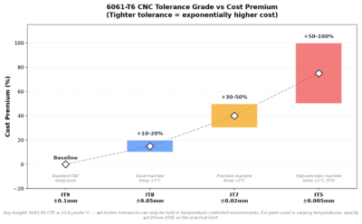
Une tolérance n'est crédible que lorsqu'elle est liée à la taille des entités, géométrie, structure de référence, état matériel, température, état de surface, et incertitude de mesure. Une capacité globale telle que +/-0.01 mm en dit peu sur un long mur mince, un petit alésage, ou une grande assiette plate. Imposer des exigences strictes uniquement aux fonctionnalités qui affectent l'ajustement ou la fonction, et définir la méthode de contrôle avant le début de l'usinage.
Exigence | Planification des processus | Planification des inspections |
Dimensions générales | Utiliser une tolérance d'atelier ou de dessin documentée | Des outils manuels calibrés peuvent suffire pour les fonctionnalités non critiques |
Fermer les alésages et les arbres | Alésage, rame, ou finition-tournage avec stock et température contrôlés | Utiliser des jauges d'alésage appropriées, jauges à air, ou une MMT selon taille et incertitude |
Poste et profil | Utilisez des données stables et minimisez les modifications de configuration | Définir la simulation de référence et évaluer le GD indiqué&Exigence T |
Planéité et parallélisme | Équilibrer l'enlèvement de matière et éviter la distorsion du serrage | Prise en charge cohérente de la pièce et prise en compte des exigences de l'état libre |
Etat de surface | Spécifier le paramètre pertinent pour le processus et le sens de mesure | Se mettre d'accord sur les paramètres de l'instrument, emplacement, couper, et règle d'acceptation |
Parois minces | Utiliser une finition à faible force et un desserrage progressif si nécessaire | Mesurer dans l'état retenu ou libre défini |
Pour les tolérances de taille et les ajustements, OIN 286-1:2010 constitue la base du système de codes ISO. Contrôles géométriques tels que la planéité, position, et le profil sont définis à travers OIN 1101:2017. Les indications de texture de surface doivent suivre le système de dessin applicable; OIN 21920-1:2021 couvre les indications de méthode de profil dans la documentation technique du produit.
Température et mesure
L'aluminium se dilate d'environ 23 à 24 um par mètre par vous C. Sur un 100 caractéristique mm, un 10 La différence de température de °C peut changer de taille d'environ 0.023 à 0.024 mm. Laissez la pièce et la jauge atteindre un niveau stable, température connue avant la mesure finale, et utiliser une méthode d'inspection dont l'incertitude est suffisamment petite pour la tolérance indiquée. JADE-CNC peut aligner ces exigences avec ses Services d'inspection CNC.
Flux de travail de validation des paramètres
- Confirmer l'alliage, caractère, formulaire de stock, géométrie des entités, tolérance, et exigences de finition.
- Sélectionnez un outil spécifique à l’aluminium et obtenez les données de départ du fournisseur.
- Calculer le régime et l'avance, puis appliquez la broche, pouvoir, titulaire, et limites de maintien.
- Entrée du programme, coins, changements d'engagement, évacuation des copeaux, et un régime maximum sûr délibérément.
- Exécutez un premier article et un outil d'enregistrement contrôlés, titulaire, surplomb, liquide de refroidissement, vitesses, se nourrit, et compensations.
- Inspecter les dimensions critiques, fils de discussion, bavures, et état de surface selon la méthode convenue.
- Ajuster une variable à la fois, libérer le processus éprouvé, et surveiller la durée de vie des outils en production.
L'optimisation des paramètres ne doit commencer qu'une fois l'itinéraire de fabrication défini. Pour les pièces en grand volume qui pourraient être coulées au lieu d'être découpées à partir de matériaux corroyés, le 6061-Comparaison de l'aluminium T6 et ADC12 explique les différences dans l'investissement en outillage, coût unitaire, propriétés, tolérances, et finition.
Comment JADE-CNC aborde l'usinage 6061-T6
JADE-CNC usine des composants 6061-T6 personnalisés à partir de prototypes jusqu'à une production répétée. La sélection des paramètres commence par la pièce plutôt que par un graphique générique: l'équipe examine l'accès aux outils, stabilité du mur, zones de tolérance, exigences de surface, points de contrôle, quantité, et la fin prévue avant de confirmer le parcours du processus.
- 3-axe, 4-axe, et itinéraires de fraisage 5 axes sélectionnés autour de l'accès aux fonctionnalités et du contrôle de configuration
- Tournage CNC, forage, tapotement, ennuyeux, et support de filetage
- Revue des montages et des séquences d'usinage pour les parois minces, assiettes, logements, et des poches profondes
- Essais de paramètres et vérifications du premier article pour les fonctionnalités critiques ou de production répétée
- Préparation des surfaces et coordination des finitions de surfacepour pièces anodisées ou cosmétiques
- Dimensionnel, fil, surface, et inspection CMM selon la portée convenue
Pour prototypes ou lots répétés, envoyer le modèle 3D, 2Dessin D, état matériel, quantité, finition, et les exigences d'inspection pour demander une revue d'usinage JADE-CNC.
Foire aux questions
Questions courantes sur les paramètres et les processus
Quelle vitesse de coupe dois-je utiliser pour l'aluminium 6061-T6?
Pour le fraisage du carbure, 200-600 m/min est une plage de planification pratique pour de nombreuses opérations d'ébauche, tandis que les processus de finition stables peuvent être plus élevés. La valeur correcte dépend du coupeur exact, revêtement, diamètre, fiançailles, broche, titulaire, liquide de refroidissement, et les données du fournisseur d’outils.
Quelle avance par dent convient à une fraise en bout 6061-T6?
De nombreuses applications de fraisage de carbure démarrent entre 0.02 et 0.15 mm/dent. Petits outils, coupes de finition, et les fonctionnalités instables utilisent la partie inférieure de la plage; les outils d'ébauche rigides plus grands peuvent utiliser la partie supérieure. Ajuster le faux-rond et l'amincissement radial des copeaux.
Quel revêtement de fraise est le meilleur pour le 6061-T6?
Carbure poli non revêtu, ZrN, et les DLC spécifiques à l'aluminium sont des choix courants. La meilleure option dépend de la géométrie de l'outil, polissage des bords, application, quantité, liquide de refroidissement, et le coût. Utilisez la recommandation du fournisseur concernant les matériaux non ferreux plutôt que de sélectionner uniquement par nom de revêtement..
Pourquoi l'aluminium se soude-t-il au tranchant?
Le bord rapporté résulte généralement d'une combinaison d'adhérence du matériau, un bord inadapté ou émoussé, frottement, chaleur, lubrification limitée, et recoupe de copeaux. Inspectez d’abord l’outil, puis examinez la charge des puces, vitesse de coupe, fiançailles, livraison de liquide de refroidissement, et évacuation.
Les pièces 6061-T6 peuvent-elles tenir +/-0.01 mm?
Certaines fonctionnalités peuvent, mais la faisabilité dépend de la taille nominale, géométrie, épaisseur de paroi, état des stocks, température, stabilité de la machine, montage, finition, et l'incertitude de l'inspection. Un examen des dessins est requis avant de traiter cette valeur comme une capacité de production.
Le liquide de refroidissement par inondation est-il toujours meilleur pour l'aluminium?
Non. Le liquide de refroidissement par inondation est efficace pour de nombreuses opérations d'ébauche et de perçage, tandis que MQL ou air peuvent convenir à une finition légère et à des processus propres. Une livraison à la pointe et une évacuation fiable des copeaux comptent plus que l'étiquette de la méthode de refroidissement.
Conclusion
L'usinage réussi du 6061-T6 repose sur un outil tranchant spécifique à l'aluminium., une charge de copeaux significative, engagement stable, évacuation fiable des copeaux, maintien contrôlé, et inspection qui correspond au dessin. Les tableaux de vitesse et d'avance sont utiles pour estimer un point de départ, mais ils ne peuvent pas remplacer les données spécifiques à l'outil et un premier article vérifié.
Documenter l'outil publié, titulaire, surplomb, méthode de refroidissement, RPM, alimentation, fiançailles, parcours d'outil, compensations, et les résultats des inspections. Ce record est ce qui transforme une bonne coupe test en un processus de production reproductible..
Articles connexes sur le 6061-T6
- 6061-Guide complet d'usinage CNC en aluminium T6
- 6061-T6 contre aluminium 7075-T6: Force, Coût & Usinabilité
- 6061-Anodisation de l'aluminium T6: Espèces, Couleurs, Épaisseur & Règles de conception
- 6061-Paramètres d'usinage CNC T6: Vitesses, Flux, Outillage & Contrôle des processus
- 6061-T6 contre ADC12 Aluminium: Usinage CNC ou moulage sous pression?
- 6061-Directives DFM pour l'usinage CNC T6: Règles de conception & Liste de contrôle
- 6061-Propriétés de l'aluminium T6: Mécanique, Thermique & Données chimiques

Léo Liang, Fondateur Meilleur partenaire avec R&D
LEO, fondateur de JADE-CNC, qui apporte plus de deux décennies d'expertise dans l'industrie, Leo a commencé sa carrière en tant qu'apprenti et met en pratique ses compétences en traitement de surface et en usinage CNC..
Hey there, You have done an incredible job. I’ll certainly digg it and
personally suggest to my friends. I’m sure
they will be benefited from this web site.
I will be Happy if the article can help you somewhere, thanks!