


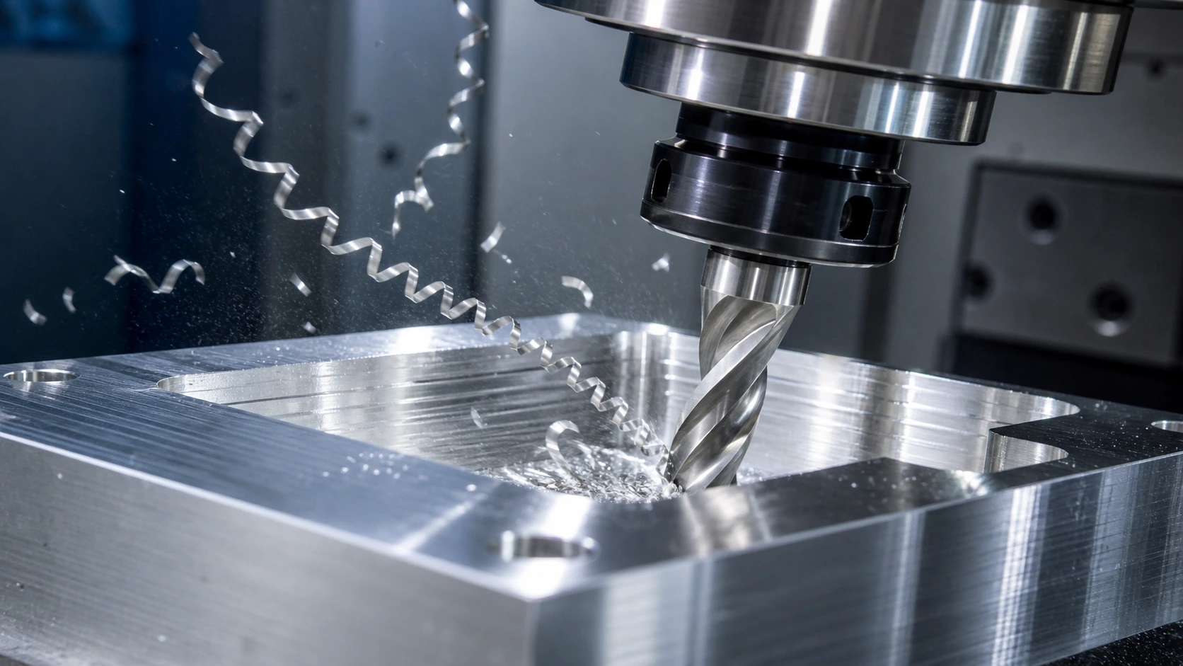
Практичные стартовые диапазоны для фрезерования, бурение, постукивание, и токарная обработка алюминия 6061-T6, с руководством по оснастке, контроль чипа, тонкие стены, допуски, and process validation.
Введение
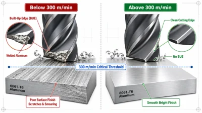
6061-T6 is forgiving compared with many engineering metals, but it still rewards a disciplined process. A sharp tool can remove material quickly and leave a clean finish. The same alloy can also produce built-up edge, welded chips, картавит, chatter, or dimensional drift when the cutter, chip load, engagement, охлаждение, and fixture do not work together.
This guide gives practical starting ranges rather than universal recipes. Final parameters depend on tool diameter and geometry, spindle power, maximum RPM, holder runout, tool overhang, radial and axial engagement, подача охлаждающей жидкости, работа, feature depth, and the required surface or tolerance. Use the tool manufacturer’s cutting data as the primary reference, then confirm the process with controlled test cuts.
For a broader material and design overview, see JADE-CNC’s 6061-T6 aluminum CNC machining guide. The sections below focus on parameter selection and shop-floor process control.
Why 6061-T6 Machines Well
6061-T6 combines moderate hardness, useful strength, good thermal conductivity, and relatively low cutting forces. It usually forms manageable chips with sharp, positive-rake tools. These characteristics support high material-removal rates and good surface quality without the severe work-hardening behavior associated with some stainless steels or nickel alloys.
Its advantages come with three process risks. Aluminum can adhere to the cutting edge, deep features can trap chips, and thin sections can deflect because the elastic modulus is much lower than that of steel. Thermal expansion also matters when dimensions are measured to a few hundredths or thousandths of a millimeter. Good machining therefore depends as much on chip evacuation, работа, and temperature as it does on spindle speed.
The underlying strength, modulus, проводимость, and expansion data are covered in the 6061-T6 aluminum properties guide. If a part needs substantially higher strength, compare the machining and cost trade-offs in 6061-T6 vs 7075-T6 aluminum before changing the cutting process.
Tool Selection for 6061-T6
Операция | Preferred tool | Geometry or coating | Selection notes |
General milling | Solid-carbide end mill | Polished uncoated, ZrN, or aluminum-specific DLC | Use a sharp edge and enough flute space for chip evacuation |
Deep pockets and slots | 2- or 3-flute carbide end mill | High helix with polished flutes | Fewer flutes provide more chip space |
Отделка | 3-flute carbide or PCD where justified | Sharp, low-friction edge | Choose low runout and a rigid holder before increasing speed |
Drilling | Carbide or polished HSS drill | Aluminum geometry; through-coolant for deep holes | Point geometry and chip evacuation matter more as depth increases |
Постукивание | Aluminum-specific spiral-flute or form tap | Polished flutes or suitable surface treatment | Select the tap and pilot hole for thread class and engagement |
Turning | Positive-rake polished carbide insert | Sharp, nonferrous grade | Use a stable setup and control long stringy chips |
Precision boring or reaming | Carbide boring tool or reamer | Sharp edge and minimal runout | Leave a consistent allowance and verify at controlled temperature |
End Mill Flute Count
Two-flute cutters provide generous chip space and are useful for narrow slots, глубокие карманы, and machines with limited air or coolant delivery. Three-flute cutters often give a strong balance of chip clearance, rigidity, and productivity for general aluminum milling. Four or more flutes can work well for light finishing or high-speed strategies when the flute valleys and evacuation system can keep up with chip volume.
Tool Geometry and Edge Condition
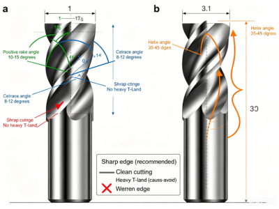
Choose a sharp, positive-rake cutting edge with polished flutes and enough clearance to avoid rubbing. Aluminum-specific tools commonly use a high helix and a large polished gullet. Heavy edge preparation can increase cutting force and encourage material adhesion on 6061-T6, while an edge that is too fragile may chip in an interrupted or unstable cut. Tool geometry should match the operation, not just the alloy name.
Coating Choice
Polished uncoated carbide, ZrN, and low-friction aluminum-specific DLC coatings are common choices. PCD can be economical in stable production where long edge life and consistent finish justify the tool cost. Do not reject or approve a coating by name alone: coating composition, surface smoothness, подготовка кромок, and the tool supplier’s intended material group all matter.
How to Calculate RPM and Feed Rate
Core Formulas
Spindle speed (об/мин) = (cutting speed Vc x 1000) / (pi x tool diameter D)
Table feed (mm/min) = RPM x number of teeth z x feed per tooth fz
For a 10 мм, three-flute end mill at Vc = 400 m/min and fz = 0.06 mm/tooth, the calculated spindle speed is about 12,700 RPM and the table feed is about 2,290 mm/min. If the spindle is limited to 10,000 об/мин, preserve the intended chip load by starting near 1,800 mm/min rather than keeping the original feed and allowing the tool to rub.
Tool diameter | RPM at Vc 250 m/min | RPM at Vc 400 m/min | RPM at Vc 600 m/min |
3 мм | 26,500 | 42,400 | 63,700 |
6 мм | 13,300 | 21,200 | 31,800 |
10 мм | 8,000 | 12,700 | 19,100 |
16 мм | 5,000 | 8,000 | 11,900 |
20 мм | 4,000 | 6,400 | 9,500 |
Rounded calculations. Confirm the cutter’s maximum RPM, holder rating, spindle power, and machine limits before use.
Chip Load Is Not the Whole Story
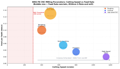
Feed per tooth is a starting variable, not a complete description of the cut. Radial chip thinning can reduce actual chip thickness at low radial engagement, while tool runout can make one flute carry most of the load. Entry moves, corners, plunges, ramps, and changes in engagement may need separate feed control. CAM simulation and toolpath smoothing are especially useful in deep pockets and thin-wall work.
Milling Speeds and Feeds
The following ranges are intended for sharp carbide tools in a rigid CNC setup. Start near the lower end when the tool is small, overhang is long, engagement is heavy, chip evacuation is restricted, or the fixture is flexible. Higher values require suitable tooling, balance, возможности шпинделя, and process evidence.
Операция | Cutting speed Vc (m/min) | Feed per tooth fz (mm/tooth) | Starting engagement |
Full-width slotting | 200-350 | 0.03-0.08 | ap 0.3-1.0 x D; ae 1.0 x D |
Side milling / roughing | 250-500 | 0.04-0.12 | ap 0.5-1.5 x D; ae 0.2-0.6 x D |
Adaptive roughing | 300-600 | 0.04-0.15 | ap 1.0-2.0 x D; ae 0.08-0.25 x D |
Semi-finishing | 350-700 | 0.03-0.08 | 0.2-0.5 mm stock; ae 0.1-0.3 x D |
Отделка | 400-1000 | 0.02-0.06 | 0.05-0.30 mm stock; ae 0.05-0.2 x D |
Starting ranges for planning only. D = cutter diameter. Supplier data and test cuts control the released process.
Roughing Strategy
Constant-engagement or adaptive toolpaths can maintain a more stable cutter load than conventional pocketing, particularly at internal corners. Use enough axial depth to engage the useful flute length, but keep radial engagement within the tool and spindle’s capacity. A slot is a much heavier cut than a side-milling pass at the same speed and feed, so the two should not share parameters automatically.
Finishing Strategy
Leave a uniform amount of material for finishing and use the shortest practical tool. A clean-up pass cannot correct a wall that was already pushed out of position during roughing. For visible surfaces, keep cutter marks consistent and decide whether the part will remain as machined or receive anodizing, дробеструйная обработка, or another finish. The 6061-T6 aluminum anodizing guide explains how machined texture, толщина покрытия, маскировка, and appearance requirements affect the final part. JADE-CNC reviews this transition through its Фрезерные услуги с ЧПУ and finishing support.
Drilling Parameters
Drill diameter | Cutting speed (m/min) | Feed (mm/rev) | Process note |
Below 3 мм | 80-150 | 0.02-0.06 | Runout and chip packing dominate; use short pecks if needed |
3-5 мм | 100-180 | 0.05-0.10 | Spot only when required by geometry or drill design |
5-10 мм | 120-250 | 0.08-0.20 | Use coolant or air to prevent chip recutting |
10-20 мм | 150-300 | 0.15-0.30 | Check machine power and through-coolant capability |
Above 20 мм | 150-300 | 0.20-0.40 | Pilot, indexable, or helical interpolation may be more stable |
Ranges assume a suitable carbide or polished HSS drill. Follow the drill maker’s diameter-specific data when available.
Deep Holes
Hole depth changes the process. As the depth-to-diameter ratio increases, chips have farther to travel and coolant has less access to the cutting edge. Through-coolant drills are preferred for demanding deep holes. Pecking can help some tools and machines, but excessive short pecks increase cycle time and may rub or recut chips. Use the drill manufacturer’s recommended cycle and keep the flute path clear.
Hole Accuracy
Drilling alone may not satisfy a close diameter, округлость, straightness, or position requirement. A practical route may include drilling undersize, then boring or reaming with a consistent allowance. Spotting is useful when the entry surface, location requirement, or drill design calls for it, but an incorrect spot angle can damage a modern carbide drill’s outer corners.
Tapping and Thread Milling
Coarse thread | Подача / synchronized feed (mm/rev) | Typical cutting-tap speed (m/min) | Pilot-hole note |
M3 x 0.5 | 0.50 | 8-20 | Confirm percentage of thread and tap supplier chart |
M4 x 0.7 | 0.70 | 8-20 | Use adequate depth beyond the full thread where possible |
M5 x 0.8 | 0.80 | 10-25 | Use polished flutes and suitable lubricant |
M6 x 1.0 | 1.00 | 10-25 | Rigid tapping feed equals thread pitch |
M8 x 1.25 | 1.25 | 10-30 | Reduce speed for deep blind holes |
M10 x 1.5 | 1.50 | 10-30 | Clear chips before reversing a cutting tap |
M12 x 1.75 | 1.75 | 10-30 | Check torque, engagement length, and coolant access |
The synchronized feed for rigid tapping equals the thread pitch. Cutting speed varies with tap design, lubrication, hole depth, and machine synchronization.
Cut Taps, Form Taps, and Thread Mills
Cut taps create chips and need an evacuation path. Form taps displace material without chips but require a different pilot diameter and suitable ductility, крутящий момент, and lubrication. Thread mills offer diameter control, low reversal torque, and a safer failure mode on valuable parts, although they require interpolation and usually more cycle time. Choose the method from thread size, глубина, сорт, количество, machine capability, and inspection plan.
A generic pilot-hole formula is not a substitute for the selected tap’s chart. Specify the thread system and class, confirm the desired percentage of engagement, and gauge the completed thread with the agreed plug or functional gauge.
Turning Parameters
Операция | Cutting speed (m/min) | Feed (mm/rev) | Depth of cut (мм) |
Rough turning | 250-600 | 0.15-0.40 | 1.0-4.0 |
Finish turning | 400-1000 | 0.05-0.15 | 0.10-0.50 |
Grooving / parting | 150-350 | 0.04-0.15 | Tool-width dependent |
Single-point threading | 50-200 | Thread pitch | Multiple controlled passes |
Use a positive-rake polished insert intended for nonferrous materials. Adjust for insert geometry, work diameter, rigidity, and chip control.
In turning, surface speed changes with diameter, so constant-surface-speed control can improve consistency within the spindle limit. Use a maximum RPM clamp, particularly near the centerline. Long chips can damage the surface or create a safety hazard; select an insert geometry and feed that produce manageable chips, and use directed coolant when appropriate.
Cooling, Lubrication, and Chip Evacuation
Метод | Where it works well | Main benefit | Main limitation |
Flood coolant | General roughing, бурение, and chip-heavy work | Cooling, lubrication, and chip transport | Concentration, maintenance, and part cleanliness must be controlled |
Through-tool coolant | Deep drilling and difficult chip evacuation | Moves chips out of the cutting zone | Requires compatible tools, holders, and pressure |
MQL | Light milling, постукивание, and clean-process work | Good boundary lubrication with little fluid | Limited bulk cooling for heavy material removal |
Air blast | Отделка, тонкие стены, and dry processes | Keeps chips away without liquid contamination | Provides little lubrication and must be safely contained |
Air plus MQL | Pockets and finish milling | Combines chip transport with lubrication | Mist collection and consistent delivery are important |
The best system is the one that reaches the cutting edge and removes chips reliably. A large coolant volume aimed away from a deep pocket may be less effective than a directed air and lubricant stream. Keep coolant concentration and cleanliness stable, because inconsistent lubrication can change BUE behavior and stain aluminum surfaces before finishing.
Fixturing and Thin-Wall Control
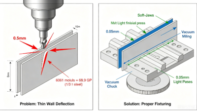
Thin 6061-T6 walls can move under clamp load, cutting force, residual stress, and heat. The fixture should locate the part repeatably without forcing it into an artificial shape that springs back after release. The 6061-T6 CNC machining DFM guidelines provide additional rules for walls, карманы, radii, дыры, нити, and tolerance allocation. JADE-CNC custom CNC machining review considers stock condition, datum choice, access, support, and machining sequence together.
- Use broad, repeatable contact areas and apply only the clamping force needed for stability.
- Rough opposing sides in a balanced sequence when large amounts of material are removed.
- Leave uniform finish stock and allow the part to stabilize before the final pass.
- Support thin walls with soft jaws, приспособления, sacrificial material, or vacuum workholding when appropriate.
- Reduce radial engagement, shorten tool overhang, and avoid sudden direction changes near flexible features.
- Define whether critical dimensions are inspected while restrained or in the free state.
Troubleshooting Common Machining Problems
Проблема | Likely causes | Practical checks |
Built-up edge | Dull or unsuitable edge, low effective speed, rubbing, poor lubrication, перерезка стружки | Inspect the edge, confirm chip load, improve lubrication and evacuation, then adjust speed |
Poor surface finish | Runout, chatter, BUE, износ инструмента, excess feed, unstable stock | Check holder and spindle, shorten overhang, stabilize the part, and leave uniform finish stock |
Heavy burrs | Dull edge, weak exit support, unsuitable toolpath, excess feed at breakthrough | Use a sharp tool, support the exit, change cut direction, and apply a controlled edge break |
Chip welding | Hot recut chips, restricted flute space, poor coolant delivery | Use an aluminum-specific tool, add chip space, and improve air or coolant access |
Thin-wall movement | Clamping distortion, residual stress, excess cutting force, нагревать | Balance stock removal, reduce engagement, support the wall, and finish after the part stabilizes |
Hole size drift | Drill runout, нагревать, built-up edge, unstable entry, worn reamer | Check runout, use a controlled entry, leave consistent reaming stock, and verify temperature |
Tap failure | Incorrect pilot, chip packing, misalignment, high torque, insufficient lubricant | Verify pilot size and thread depth, use rigid synchronization, clear chips, and select the correct tap style |
Change one variable at a time during troubleshooting and record the result. Raising spindle speed, reducing feed, changing coolant, and replacing the tool simultaneously may improve the part, but it does not reveal the cause. A short controlled trial is easier to repeat and transfer into production.
Achieving Tight Tolerances
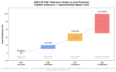
A tolerance is credible only when it is tied to feature size, геометрия, базовая структура, материальное состояние, температура, обработка поверхности, and measurement uncertainty. A blanket capability such as +/-0.01 mm says little about a long thin wall, a small bore, or a large flat plate. Put tight requirements only on features that affect fit or function, and define the inspection method before machining begins.
Требование | Process planning | Inspection planning |
General dimensions | Use a documented shop or drawing tolerance | Calibrated hand tools may be sufficient for noncritical features |
Close bores and shafts | Bore, ream, or finish-turn with controlled stock and temperature | Use suitable bore gauges, air gauges, or a CMM according to size and uncertainty |
Position and profile | Use stable datums and minimize setup changes | Define datum simulation and evaluate the stated GD&T requirement |
Flatness and parallelism | Balance material removal and avoid clamping distortion | Support the part consistently and account for free-state requirements |
Surface texture | Specify the process-relevant parameter and measurement direction | Agree on instrument settings, location, cutoff, and acceptance rule |
Тонкие стены | Use low-force finishing and staged unclamping where needed | Measure in the defined restrained or free condition |
For size tolerances and fits, ИСО 286-1:2010 provides the basis of the ISO code system. Geometrical controls such as flatness, позиция, and profile are defined through ИСО 1101:2017. Surface texture indications should follow the applicable drawing system; ИСО 21920-1:2021 covers profile-method indications in technical product documentation.
Temperature and Measurement
Aluminum expands by roughly 23 к 24 um per meter per deg C. On a 100 mm feature, а 10 deg C temperature difference can change size by about 0.023 к 0.024 мм. Let the part and gauge reach a stable, known temperature before final measurement, and use an inspection method whose uncertainty is small enough for the stated tolerance. JADE-CNC can align these requirements with its CNC inspection services.
Parameter Validation Workflow
- Confirm alloy, характер, складская форма, feature geometry, терпимость, и требования к отделке.
- Select an aluminum-specific tool and obtain the supplier’s starting data.
- Calculate RPM and feed, then apply spindle, power, holder, and workholding limits.
- Program entry, corners, engagement changes, chip evacuation, and safe maximum RPM deliberately.
- Run a controlled first article and record tool, holder, overhang, охлаждающая жидкость, speeds, feeds, and offsets.
- Inspect critical dimensions, нити, картавит, and surface condition using the agreed method.
- Adjust one variable at a time, release the proven process, and monitor tool life in production.
Parameter optimization should begin only after the manufacturing route is settled. For high-volume parts that could be cast instead of cut from wrought stock, тот 6061-T6 vs ADC12 aluminum comparison explains the differences in tooling investment, unit cost, properties, допуски, and finishing.
How JADE-CNC Approaches 6061-T6 Machining
JADE-CNC machines custom 6061-T6 components from prototypes through repeat production. Parameter selection begins with the part rather than a generic chart: the team reviews tool access, wall stability, зоны допуска, требования к поверхности, контрольные точки, количество, and the planned finish before confirming the process route.
- 3-ось, 4-ось, and 5-axis milling routes selected around feature access and setup control
- Токарная обработка с ЧПУ, бурение, постукивание, скучный, and thread-milling support
- Fixture and machining-sequence review for thin walls, тарелки, корпуса, and deep pockets
- Parameter trials and first-article checks for critical or repeat-production features
- Surface preparation and координация отделки поверхностиfor anodized or cosmetic parts
- Dimensional, thread, surface, and CMM inspection according to the agreed scope
For prototypes or repeat batches, пришлите 3D модель, 2D рисунок, материальное состояние, количество, заканчивать, and inspection requirements to request a JADE-CNC machining review.
Часто задаваемые вопросы
Common Parameter and Process Questions
What cutting speed should I use for 6061-T6 aluminum?
For carbide milling, 200-600 m/min is a practical planning range for many roughing operations, while stable finishing processes may run higher. The correct value depends on the exact cutter, покрытие, диаметр, engagement, spindle, holder, охлаждающая жидкость, and tool supplier’s data.
What feed per tooth is suitable for a 6061-T6 end mill?
Many carbide milling applications start between 0.02 и 0.15 mm/tooth. Small tools, finishing cuts, and unstable features use the lower part of the range; larger rigid roughing tools may use the upper part. Adjust for runout and radial chip thinning.
Which end mill coating is best for 6061-T6?
Polished uncoated carbide, ZrN, and aluminum-specific DLC are common choices. The best option depends on tool geometry, edge polish, application, количество, охлаждающая жидкость, и стоимость. Use the supplier’s nonferrous recommendation rather than selecting by coating name alone.
Why does aluminum weld to the cutting edge?
Built-up edge usually results from a combination of material adhesion, an unsuitable or dull edge, rubbing, нагревать, limited lubrication, and chip recutting. Inspect the tool first, then review chip load, cutting speed, engagement, подача охлаждающей жидкости, and evacuation.
Can 6061-T6 parts hold +/-0.01 мм?
Some features can, but feasibility depends on nominal size, геометрия, толщина стенки, состояние запаса, температура, machine stability, приспособление, отделка, and inspection uncertainty. A drawing review is required before treating that value as a production capability.
Is flood coolant always better for aluminum?
Нет. Flood coolant is effective for many roughing and drilling operations, while MQL or air may suit light finishing and clean processes. Delivery at the cutting edge and reliable chip removal matter more than the label of the cooling method.
Заключение
Successful 6061-T6 machining is built around a sharp aluminum-specific tool, a meaningful chip load, stable engagement, reliable chip evacuation, controlled workholding, and inspection that matches the drawing. Speed and feed tables are useful for estimating a starting point, but they cannot replace tool-specific data and a verified first article.
Document the released tool, holder, overhang, coolant method, об/мин, feed, engagement, toolpath, offsets, and inspection results. That record is what turns a good test cut into a repeatable production process.
Статьи по теме 6061-T6
- 6061-Полное руководство по обработке алюминия T6 с ЧПУ
- 6061-T6 против 7075-T6 Алюминий: Сила, Расходы & Обрабатываемость
- 6061-T6 Анодирование алюминия: Типы, Цвета, Толщина & Правила проектирования
- 6061-T6 против ADC12 Алюминий: Обработка с ЧПУ или литье под давлением?
- 6061-T6 Обработка на станке с ЧПУ Рекомендации DFM: Правила проектирования & Контрольный список
- 6061-Свойства алюминия T6: Механический, Термальный & Химические данные

Лео Лян, Founder Best Partner with R&D
Основатель JADE-CNC Лео, который обладает более чем двадцатилетним опытом работы в отрасли, Лео начал свою карьеру в качестве ученика и практиковал свои навыки в области обработки поверхностей и обработки на станках с ЧПУ..