



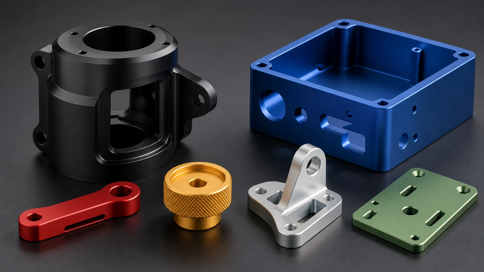
Praktyczny przewodnik inżynieryjny dotyczący typu I, Typ II, i anodowanie typu III, kontrola koloru, grubość powłoki, naddatek wymiarowy, maskowanie, opieczętowanie, kontrola, i wymagania dotyczące rysunku.
Wstęp
6061-T6 jest szeroko stosowany do anodowanych części CNC, ponieważ łączy w sobie dobre zachowanie podczas obróbki z ogólnie jednolitą reakcją na anodowanie. Anodowanie może poprawić odporność na korozję, zapewnić twardszą powierzchnię, stworzyć dekoracyjny kolor, i izoluje elektrycznie wybrane obszary. Korzyści te zależą od wyboru odpowiedniego procesu i jego jasnego określenia.
Wykończenie należy zaplanować przed obróbką, nie dodano po namyśle. Grubość powłoki zmienia wymiary, obróbka wstępna zmienia wygląd, każda część wymaga kontaktu ze stojakiem, i barwione kolory różnią się w zależności od stopu, tekstura, grubość folii, stan kąpieli, i uszczelnienie. JADE-CNC analizuje te czynniki w ramach swojego procesu wsparcie w wykańczaniu powierzchni do obrabianych części aluminiowych.
Dla szerszej zależności pomiędzy wyborem stopu, obróbka, tolerancje, wykończeniowy, i koszt, zacznij od 6061-Kompletny przewodnik po obróbce aluminium CNC T6.
Co anodowanie robi z aluminium 6061-T6
Anodowanie to proces konwersji elektrochemicznej. Część aluminiowa pełni rolę anody w ogniwie elektrolitycznym, a jego powierzchnia przekształca się w tlenek glinu. W przeciwieństwie do farby lub platerowania, warstwa anodowa nie jest po prostu osadzana na wierzchu metalu. Część tlenku tworzy się pod pierwotną powierzchnią, a część gromadzi się na zewnątrz.
Powstały tlenek jest porowaty przed uszczelnieniem. Pory te umożliwiają dekoracyjne barwienie, ale oznaczają one również, że uszczelnienie i obróbka końcowa muszą odpowiadać zamierzonej usłudze. Uszczelniona powłoka dekoracyjna, niezabezpieczona twarda powłoka zapewniająca maksymalną odporność na ścieranie, i zamaskowany interfejs elektryczny to trzy różne specyfikacje techniczne.
Typowa sekwencja procesu
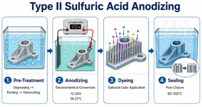
- Oczyść część i usuń płyny obróbkowe, odciski palców, i pozostałość.
- Zastosować wymaganą mechaniczną lub chemiczną obróbkę wstępną.
- Rozłóż część, aby zapewnić kontakt elektryczny i podtrzymać drenaż.
- Anodować do określonego typu i grubości powłoki.
- Pokoloruj porowatą folię, jeśli wymagane jest wykończenie barwione lub elektrolitycznie.
- Uszczelnij powłokę, gdy specyfikacja i warunki użytkowania wymagają uszczelnienia.
- Sprawdź wygląd, grubość, wymiary, wątki, maskowanie, oraz wszelkie określone testy wydajności.
Scena | Co się stanie | Co inżynierowie powinni kontrolować |
Czyszczenie | Olej, płyn chłodzący, odciski palców, i pozostałości warsztatowe są usuwane | Ślepe otwory, uwięziony płyn, wstawki, i zanieczyszczenie |
Obróbka wstępna | Akwaforta, odmutowanie, strzałowy, szczotkowanie, lub polerowanie utrwala powierzchnię | Kosmetyczne twarze, tekstura, jednolitość zapasów, i stan krawędzi |
Dręczący | Styk elektryczny przewodzi prąd i podtrzymuje część | Lokalizacja znaku stojaka, drenaż, orientacja, i obszar kontaktu |
Anodowanie | Powierzchnia aluminium przekształca się w porowaty tlenek glinu | Rodzaj powłoki, grubość, stop, bieżąca dystrybucja, i sterowanie kąpielą |
Kolorowanie | Jeśli jest to określone, stosuje się barwnik lub barwnik elektrolityczny | Zatwierdzona próbka, zakres kolorów, grubość folii, i spójność partii |
Opieczętowanie | Pory są zamknięte, aby poprawić korozję i zachowanie koloru | Metoda uszczelnienia, wymagania dotyczące zużycia, stabilność barwnika, i obowiązująca specyfikacja |
Kontrola | Wygląd, grubość, wymiary, wątki, i określone testy są sprawdzane | Kryteria akceptacji i miejsca testów określone przed produkcją |
Typ I, Typ II, i anodowanie typu III
Znany typ I, II, i III pochodzą z MIL-PRF-8625. Specyfikacja uwzględnia także dodatkowe podtypy i wyodrębnia klasę 1 powłoki, które nie są celowo farbowane, z klasy 2 powłoki, które są barwione lub pigmentowane. Rysunek powinien zawierać nazwę obowiązującego standardu, typ, klasa, grubość, kolor, opieczętowanie, maskowanie, i wymagał testów, zamiast polegać na słowie „anodowanie”.’ sam.
Typ anodowania | Rodzina procesów | Typowy zakres grubości | Typowy powód, aby to określić |
Typ I | Kwas chromowy | Cienki, często o 0.5-7.5 jeden | Specyfikacje lotnicze lub starsze; części wrażliwe na zmęczenie i złożone |
Typ II | Kwas siarkowy | Często 5-25 jeden | Kolor dekoracyjny, zabezpieczenie antykorozyjne, i ogólne części CNC |
Typ III | Anodowanie twarde siarkowe | Często 25-50 jeden; możliwe są szersze zakresy | Odporność na zużycie, twardsze powierzchnie, i funkcjonalne części inżynieryjne |
Zakresy stanowią praktyczne odniesienia, a nie uniwersalne granice. Obowiązujący rysunek i specyfikacja kontrolują ostateczne wymagania.
Typ I: Anodowanie kwasem chromowym
Typ I wytwarza stosunkowo cienką powłokę i ma długą historię w zastosowaniach lotniczych, w tym o skomplikowanych kształtach i niektórych częściach wrażliwych na zmęczenie. Ponieważ tradycyjna chemia typu I wykorzystuje sześciowartościowy chrom, Należy dokonać przeglądu wymogów środowiskowych i regulacyjnych. Niechromowe alternatywy typu IC istnieją zgodnie z normą MIL-PRF-8625, nie należy ich jednak traktować jako automatycznie wymiennych z typem I bez zatwierdzenia.
Typ II: Anodowanie kwasem siarkowym
Typ II jest zwykle wybierany w przypadku części dekoracyjnych i ochronnych 6061-T6. Obsługuje wykończenia bezbarwne lub naturalne oraz szeroką gamę barwników, zapewniając jednocześnie użyteczną odporność na korozję i obsługę. Grubość powłoki jest zwykle wybierana w zależności od ekspozycji eksploatacyjnej, wygląd, naddatek wymiarowy, i mającą zastosowanie specyfikacją, a nie samym kolorem.
Typ III: Twarde anodowanie
Typ III wykorzystuje ściślejszą kontrolę temperatury i prądu, aby zbudować grubszy, twardsza powłoka dla odpornych na zużycie powierzchni funkcjonalnych. Naturalna powłoka może wydawać się szara, brązowy, brązowy, lub prawie czarny w zależności od stopu i grubości. Możliwe są ciemne barwniki, ale jasne kolory kosmetyczne nie są niezawodnym oczekiwaniem w postaci twardej powłoki. Uszczelnienie jest zależne od usługi, ponieważ może poprawić zachowanie korozyjne, zmieniając jednocześnie odporność na ścieranie.
Kontrola procesu typu II
Czyszczenie, Akwaforta, i Desmutting
Czyszczenie usuwa olej i zanieczyszczenia warsztatowe. Trawienie alkaliczne może zmniejszyć niewielkie różnice wizualne i stworzyć matową powierzchnię, ale usuwa również materiał i może zmiękczyć krawędzie lub zmienić wymiary. Desmutting usuwa pozostałości pierwiastków stopowych pozostałych po trawieniu. Dokładna chemia, temperatura, i czas zależą od procesora i powinny zostać sprawdzone dla stopu, geometria części, i pożądany wygląd.
Regały i dystrybucja prądu
Regały to decyzja zarówno elektryczna, jak i kosmetyczna. Punkt styku pozostawi ślad w stojaku, a gęstość prądu może koncentrować się na krawędziach, wątki, lub cienkie występy. Określ akceptowalną lokalizację stojaka na częściach o krytycznym znaczeniu dla wyglądu i umożliwij drenaż z niewidocznych elementów. Duże powierzchnie, głębokie kieszenie, i gęsto zagnieżdżone części mogą wymagać specjalnej orientacji lub styków pomocniczych.
Barwienie i uszczelnianie
Kolor barwnika zależy od struktury porów, grubość powłoki, stężenie barwnika, stan kąpieli, czas zanurzenia, i powierzchnią pod powłoką. Uszczelnianie zamyka lub modyfikuje pory, aby poprawić odporność na korozję i zachować kolor. Typowe metody obejmują gorącą wodę, octan niklu, i uszczelnianie chemiczne w niższych temperaturach, ale obowiązująca specyfikacja i wymagania dotyczące wydajności powinny określać metodę.
Grubość powłoki i zmiana wymiarów
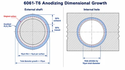
Wspólne 50/50 reguła jest przydatna dla wczesnego DFM: w przybliżeniu połowa grubości tlenku jest traktowana jako nawarstwienie na zewnątrz, a połowa jako penetracja pierwotnej powierzchni. To jest oszacowanie, nie jest uniwersalnym współczynnikiem konwersji. Stop, rodzaj anodowania, grubość, kontrola kąpieli, obróbka wstępna, and processor practice can change the relationship, szczególnie do twardego anodowania.
Określona powłoka | Wspólny kosztorys projektowy | Efekt przybliżonej średnicy | Ważna uwaga |
10 hmm typ II | O 5 hm, wzrost zewnętrzny na powierzchnię | +10 hmm na wale; -10 hm, na nudzie | Sprawdź współczynnik wzrostu za pomocą procesora |
20 hmm typ II | O 10 hm, wzrost zewnętrzny na powierzchnię | +20 hmm na wale; -20 hm, na nudzie | Może wpływać na ataki, wątki, i gniazda łożyskowe |
25 hm, typ III | O 12.5 hm, wzrost zewnętrzny na powierzchnię | +25 hmm na wale; -25 hm, na nudzie | Actual buildup can vary with the hardcoat process |
50 hm, typ III | O 25 hm, wzrost zewnętrzny na powierzchnię | +50 hmm na wale; -50 hm, na nudzie | Use processor-confirmed allowance on precision features |
Założono przybliżone przykłady projektów 50% nagromadzenie zewnętrzne. Confirm final machining allowance with the selected anodizing source.
Wały, Otwory, Sloty, i pasuje
Jeśli 10 um, powłoka wytwarza około 5 um wzrostu zewnętrznego na powierzchnię, średnica zewnętrzna wzrasta o ok 10 hm, a średnica wewnętrzna zmniejsza się o około 10 jeden. Dlatego łożyska siedzeń, otwory na kołki, średnice uszczelnień, precyzyjne szczeliny, i pasowania wtłaczane powinny być wymiarowane pod kątem stanu gotowego i sprawdzane w trakcie niestandardowa obróbka CNC.
Wątki
Strategia wątku zależy od funkcji. Maskowanie zachowuje oryginalne dopasowanie i czystą przewodność, ale pozostawia gwint bez ochrony. Naddatek na obróbkę może utrzymać pokrycie gwintu, wymaga to jednak porozumienia w sprawie nawarstwiania się powłoki. Ściganie po anodowaniu przywraca dopasowanie, ale usuwa część lub całość tlenku z boków gwintu. Przedstaw zamierzoną metodę na rysunku, zamiast pozostawiać ją interpretacji produkcyjnej.
Opcje kolorów i spójność kolorów
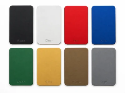
Typ II 6061-T6 może być produkowany w kolorze naturalnym lub przezroczystym, czarny, niebieski, czerwony, zielony, złoto, brązowy, szary, oraz inne systemy barwników oferowane przez przetwórcę. „Przezroczysty anod’ nie jest bezbarwny w sensie optycznym: chemia stopów, grubość folii, obróbka wstępna, i uszczelnienie może zmienić ostateczny odcień szarości lub srebra.
Nie należy obiecać dokładnego dopasowania kolorów Pantone lub ekranu bez fizycznych próbek zatwierdzonych i określonej metody pomiaru. Anodowany metal jest odblaskowy i kierunkowy, tak postrzegany kolor zmienia się wraz z połyskiem, tekstura, kąt widzenia, i oświetlenie. Do zgromadzeń, tam, gdzie jest to praktyczne, używaj tego samego stopu i źródła półproduktu, konsekwentnie obrabiaj powierzchnie, i wykończ widoczne części w jednej kontrolowanej partii.
Alloy chemistry and stock condition influence both strength and finishing response. The 6061-Przewodnik po właściwościach aluminium T6 zapewnia odpowiednią mechanikę, termiczny, i dane chemiczne. Gdy rozważana jest większa wytrzymałość, opublikowane 6061-Porównanie aluminium T6 i 7075-T6 explains the associated differences in machinability, koszt, zachowanie korozyjne, i anodowanie oczekiwań.
Określ wygląd za pomocą próbek i tolerancji
- Zidentyfikuj powierzchnie kosmetyczne i akceptowalną lokalizację znaków stojaka.
- Zdefiniuj obróbkę wstępną: jako obrobione, koralik wypalony, szczotkowane, błyszczący, lub inna kontrolowana tekstura.
- W przypadku prac, w których wygląd ma kluczowe znaczenie, należy używać zatwierdzonej próbki fizycznej lub zakresu kolorów.
- Jeśli wymagana jest instrumentalna kontrola koloru, zdefiniować przestrzeń barw, pouczający, geometria, stan połysku, i tolerancję akceptacji.
- Zachowaj stop, hartować, przygotowanie powierzchni, grubość powłoki, barwnik, i uszczelnienie spójne w częściach porównawczych.
Przygotowanie powierzchni przed anodowaniem
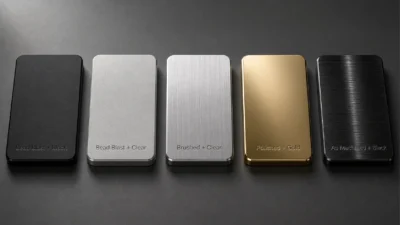
Anodowanie podąża za metalem bazowym; nie kryje zadrapań, falistość, wgniecenia, lub niespójne ścieżki narzędzi. Dlatego przygotowanie powierzchni musi być częścią procesu obróbki i wykańczania. JADE-CNC może sprawdzić przejście z obróbka aluminium CNC do wystrzału, szczotkowanie, polerowanie, i anodowanie przed rozpoczęciem produkcji.
Stan przed anodowaniem | Typowy efekt wizualny | Główna zaleta | Główne ryzyko |
Jak obrobione | Ścieżki narzędzi pozostają widoczne | Najniższa ilość dodanego preparatu | Machining marks and local texture differences remain visible |
Koralik wysadzony | Jednolity matowy wygląd | Zmniejsza nacisk wizualny na ścieżki narzędzia | Głoska bezdźwięczna, ciśnienie, obsługiwanie, i zmienność stopu wpływają na konsystencję |
Szczotkowane | Kierunkowe ziarno liniowe | Kontrolowana tekstura dekoracyjna | Kierunek słojów i przejścia krawędzi muszą być spójne |
Błyszczący | Jasne lub odblaskowe wykończenie | Wysokiej klasy dekoracyjny wygląd | Any scratch or waviness remains visible after anodizing |
Upadł | Miękkie matowe wykończenie z wygładzonymi krawędziami | Skuteczny w przypadku odpowiednich małych części | Możliwość zmiany krawędzi, małe cechy, i szczegóły wymiarowe |
Do części, dla których wygląd ma istotne znaczenie, określić chropowatość powierzchni tylko tam, gdzie jest to funkcjonalnie przydatne. Liczbowa wartość Ra nie opisuje w pełni szczotkowanego ziarna, tekstura wybuchu, lub połysk wizualny. Próbki procesowe i kontrolowane Frezowanie CNC strategie często zapewniają lepsze wskazówki dotyczące wyglądu.
Znaki narzędzi, zadziory, i ruchy cienkościennych powinny być kontrolowane przed wykończeniem. Skorzystaj z 6061-Przewodnik po parametrach obróbki CNC T6 do przeglądu oprzyrządowania, prędkości, karmi, ewakuacja wiórów, oraz strategia przejścia wykańczającego przed anodowaniem.
Maskowanie, Wkładki, i interfejsy montażowe
Maskowanie stosuje się w przypadku kontaktu elektrycznego, precyzyjne dopasowanie, klejenie, grunt, opieczętowanie, lub montaż wymaga gołego aluminium. Typowe metody obejmują wtyczki, czapki, taśmy, i maseczki wielokrotnego użytku. Każda zamaskowana granica ma tolerancję procesu, dlatego rysunek powinien identyfikować zarówno obszar funkcjonalny, jak i akceptowalną strefę przejściową.
- Podkładki uziemiające i powierzchnie kontaktowe EMI
- Siedziska łożyskowe, otwory na kołki, precyzyjne otwory, i uszczelnianie ziem
- Wybrane gwinty i wkładki gwintowane
- Interfejsy złączy elektrycznych
- Obszary zarezerwowane do spawania, wiązanie, lub późniejsza obróbka
- Powierzchnie odniesienia lub styku, na których nie jest dozwolone nakładanie się powłoki
Wstawki stalowe, spirale, magnesy, and other dissimilar materials are usually easier to control when installed after anodizing. Jeśli muszą być obecni wcześniej, the processor should review chemical compatibility, maskowanie, uwięzione rozwiązanie, i ryzyko galwaniczne.
Zasady projektowania części anodowanych 6061-T6
Obszar projektowy | Zalecane rysowanie lub akcja DFM | Powód |
Precyzja pasuje | Define final-after-finish dimensions and confirm coating allowance | Wzrost anodowy zmienia wały, nudy, szczeliny, i luki krycia |
Wątki | Wybierz spośród maskowania, dodatek, lub pogoń po zakończeniu i podaj swój wybór | Chasing restores fit but removes coating from thread surfaces |
Powierzchnie uziemiające | Zaznacz strefy nieanodowane i zdefiniuj dopuszczalny obszar styku | Tlenek anodowy jest izolacją elektryczną |
Znaki stojaka | Zidentyfikuj miejsca kontaktu inne niż kosmetyczne | Every anodized part needs an electrical contact point |
Ślepe otwory | Provide drainage where possible and flag trapped-solution risks | Zatrzymane środki chemiczne mogą zabrudzić lub uszkodzić część |
Ostre krawędzie | Użyj praktycznych promieni lub fazowań i sprawdź gęstość prądu twardej powłoki | Powłoka może być cienka, kruchy, lub spalone na trudnych krawędziach |
Metale mieszane | Install steel inserts and dissimilar hardware after anodizing when practical | Zapobiega zanieczyszczeniu kąpieli, atak, i uwięzione rozwiązanie |
Zestawy kosmetyczne | Zakończ łączenie części w tej samej kontrolowanej partii | Zmniejsza widoczne różnice kolorów pomiędzy zmontowanymi komponentami |
Identyfikowalność materiału ma również znaczenie dla wyglądu. Różny 6061 formy produktów i dostawcy mogą reagować odmiennie, nawet jeśli oznaczenie stopu jest takie samo. The Przewodnik po materiałach do obróbki CNC stanowi przydatny punkt wyjścia, ale zamówienie zakupu powinno nadal określać wymagany formularz zapasów, hartować, i certyfikacja.
Naddatek na powłokę powinien być dostosowany do grubości ściany, pasuje, dziury, wątki, promienie, i przydział tolerancji. The 6061-Wytyczne DFM dotyczące obróbki CNC T6 połączyć te decyzje projektowe w jedną listę kontrolną dotyczącą produkcji.
Jak określić anodowanie na rysunku technicznym
Użyteczna notatka dotycząca anodowania informuje przetwórcę, co ma wykonać i w jaki sposób zostanie oceniona akceptacja. Unikaj nut takich jak „czarny anodowany”.’ bez typu, grubość, lub maskowanie informacji.
Minimalne informacje o rysunku
- Obowiązująca norma i rewizja, kiedy jest to wymagane
- Rodzaj i oznaczenie klasy lub koloru anodowania
- Wymagana grubość powłoki lub zakres grubości
- Stan zapieczętowania lub rozszczelnienia oraz dowolna określona metoda uszczelnienia
- Przygotowanie wstępne lub wymagana tekstura powierzchni
- Obszary zamaskowane i nieanodowane, łącznie z tolerancją strefy przejściowej
- Ograniczenia dotyczące lokalizacji w stojaku
- Wymiary i tolerancje obowiązujące po wykończeniu
- Próbka wyglądu, tolerancja koloru, lub kontrolowane warunki oglądania
- Wymagane kontrole i testy wydajności
Przykładowa notatka rysunkowa
Przykład: Anodowanie zgodnie z MIL-PRF-8625, Typ II, Klasa 2, czarny, 10-15 jeden; zapieczętowany. Zamaskuj zidentyfikowane podkładki uziemiające i gwinty M4. Wymiary obowiązują po wykończeniu. Znaki stojaka dozwolone tylko na oznaczonej stronie nie kosmetycznej. Kolor zgodny z zatwierdzoną próbką produkcyjną.
Przykład jest celowo konkretny, ale nie jest to wymóg uniwersalny. Dostosuj standard, grubość, opieczętowanie, kolor, i testy rzeczywistego stanu pracy.
Kontrola i rozwiązywanie problemów
Plan inspekcji
Kontrola powinna uwzględniać ryzyko rysowania. Typical checks include visual appearance under controlled lighting, grubość powłoki w uzgodnionych miejscach, wymiary po wykończeniu, mierzenie gwintu, maskowanie granic, oraz testy szczelności lub korozji, jeśli zostało to określone. JADE-CNC może koordynować te kontrole poprzez swoje Usługi kontroli CNC.
- Zmierz grubość na dostępnych, reprezentatywne obszary i zapisz metodę.
- Zmierz krytyczne gwinty i pasowania po wykończeniu.
- Sprawdź kolor i teksturę w porównaniu z zatwierdzoną próbką przy określonym oświetleniu.
- Używaj testów w komorze solnej tylko z nazwaną metodą testową, czas trwania, przygotowanie próbki, stan uszczelnienia, i kryterium akceptacji.
- Review seal quality when corrosion resistance or dye retention is critical.
Typowe wady i prawdopodobne przyczyny
- Zmiana koloru: Mieszany zapas, niespójna tekstura, zmienność grubości warstwy, stan barwnika, opieczętowanie, lub separacja partii.
- Białe plamy lub plamy: Złe płukanie, uwięziona chemia, jakość wody, obsługiwanie, lub problemy z uszczelnieniem.
- Krwawienie barwnika: Insufficient sealing or incompatible post-cleaning.
- Spalone krawędzie: Nadmierna lokalna gęstość prądu, geometria, słaby kontakt, lub niewystarczające chłodzenie.
- Niejednolity wygląd: Zanieczyszczenie, nierówna obróbka wstępna, odmiana stopu, lub uszkodzenia powierzchni.
- Ciasne gwinty lub otwory: Nie zdefiniowano naddatku powłoki ani strategii maskowania.
- Ślady stojaka na kosmetycznych twarzach: Contact location was not agreed before processing.
Anodowanie w porównaniu z innymi wykończeniami
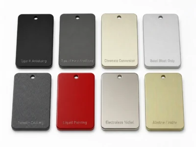
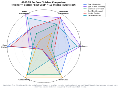
Skończyć | Najlepiej nadaje się do | Zachowanie elektryczne | Kluczowe ograniczenie |
Anodowanie typu II | Ochrona antykorozyjna i dekoracyjny kolor | Izolacyjny | Kolor i grubość wymagają kontroli procesu |
Anodowanie typu III | Odporne na zużycie powierzchnie funkcjonalne | Izolacyjny | Grubsza warstwa i ograniczona gama kolorów kosmetycznych |
Chemiczna powłoka konwersyjna | Ochrona przed korozją i kontakt elektryczny | Bardziej przewodzący niż anodowany | Wygląd i skład chemiczny zależą od określonego systemu |
Malowanie proszkowe | Gruba ochrona dekoracyjna i środowiskowa | Izolacyjny | Większa grubość i mniejsza precyzja wymiarowa |
Nikiel bezprądowy | Nosić, przewodność, i zabezpieczenie barierowe | Przewodzący | Wyższy koszt i inny tryb awarii niż anodowanie |
Gołe lub piaskowane | Tymczasowy wygląd lub kontrolowane użycie w pomieszczeniach zamkniętych | Przewodzący | Ograniczona odporność na korozję i plamy |
Anodizing is often the best fit when the substrate is aluminum and the project needs corrosion resistance, niska waga dodatkowa, kontrolowany wygląd, lub twardą powierzchnię. Nie jest to właściwa odpowiedź, gdy interfejs musi pozostać przewodzący, wymagana jest bardzo gruba warstwa dekoracyjna, or a barrier coating is preferred over a converted oxide surface.
Finish selection also depends on the manufacturing route. For higher-volume parts where die casting may replace machining from wrought plate or bar, the 6061-Porównanie aluminium T6 i ADC12 obejmuje inwestycje w oprzyrządowanie, koszt jednostkowy, właściwości, tolerancje, porowatość, i dokończenie kompromisów.
Czynniki kosztów i czasu realizacji
Anodizing cost is usually driven by minimum batch charges, rozmiar części, całkowita powierzchnia, trudność w układaniu, maskowanie, obróbka wstępna, kolor, grubość, opieczętowanie, kontrola, i odrzucić ryzyko. Stałe ceny za część lub uniwersalne mnożniki typu III nie są wiarygodne bez rysunku i ilości.
Do prototypów i obróbka CNC na małą skalę, próbki kolorów i kontrola pierwszego artykułu mogą wydłużyć czas, ale zmniejszyć ryzyko, że cała partia będzie nie do zaakceptowania pod względem wizualnym lub wymiarowym. Jeśli to możliwe, wyceń obróbkę i wykańczanie razem, tak aby maskować, dodatek, i inspekcja są zawarte w jednym planie procesu.
Jak JADE-CNC obsługuje części z anodyzowanego aluminium
JADE-CNC wspiera koordynację obróbki CNC i anodowania 6061 i inne stopy aluminium. Recenzję rozpoczynamy od rysunku i zamierzonej usługi, następnie łączy stan materialny, naddatek obróbczy, preparat kosmetyczny, maskowanie, wymagania dotyczące wykończenia, i kontrola końcowa. Jest to bardziej niezawodne niż traktowanie anodowania jako osobnego zakupu po obróbce części.
- Przegląd stopu, hartować, formularz magazynowy, i zakończ kompatybilność
- DFM do tworzenia powłoki, pasuje, wątki, cienkie ściany, lokalizacje regałów, i drenaż
- Koordynacja obróbki mechanicznej, piaskowane koralikami, szczotkowane, błyszczący, i anodowane powierzchnie
- Opcje anodowania typu II i typu III podlegają ocenie rysunku i projektu
- Przegląd maskowania podkładek uziemiających, wątki, nudy, i interfejsy montażowe
- Wymiary po wykończeniu, nitka, wygląd, i kontrolę grubości, jeśli jest to wymagane
- Pobieranie próbek prototypów i planowanie partii produkcyjnych
Wyślij model CAD, 2Rysunek D, ilość, stop, notatka o anodowaniu, wymagania kosmetyczne, i środowisko usług do JADE-CNC do poproś o przegląd wykończenia i obróbki.
Często zadawane pytania
Często zadawane pytania inżynieryjne
Czy 6061-T6 dobrze anoduje??
Tak. 6061-T6 ogólnie zapewnia jednolitą dekoracyjną i ochronną reakcję anodowania. Ostateczny wygląd nadal zależy od konsystencji zapasów, obróbka wstępna, grubość folii, barwnik, opieczętowanie, i obsługa.
Jak bardzo anodowanie zmienia wymiary?
Powszechnie stosowane wczesne szacunki zakładają, że około połowa grubości powłoki gromadzi się na zewnątrz. Dla 10 hm, powłoka, to sugeruje o 5 hm, wzrost na powierzchnię. Potwierdź faktyczny limit u procesora, zwłaszcza dla typu III.
Czy otwory gwintowane należy zamaskować?
To zależy od korozji, przewodność, klasa wątku, grubość powłoki, i potrzeby montażowe. Maskowanie, naddatek obróbczy, i pościg po mecie wymagają kompromisów, które należy przedstawić na rysunku.
Można anodować 6061 pasować dokładnie do koloru Pantone?
Możliwy jest bliski cel wizualny, ale dokładne dopasowanie różnych materiałów jest trudne, ponieważ anodowany metal jest odblaskowy i zależny od tekstury. Użyj fizycznej próbki do zatwierdzenia i określonej metody akceptacji.
Można spawać 6061 zespoły należy anodować?
Tak, jednak metal spoiny i obszary narażone na działanie ciepła mogą wykazywać inny odcień. Stop wypełniający, mieszanie spoin, obróbka wstępna, a zatwierdzenie próbki należy sprawdzić pod kątem prac kosmetycznych.
Czy twarde anodowanie jest zawsze uszczelnione?
NIE. Uszczelnienie zależy od specyfikacji i usługi. Może poprawić odporność na korozję, ale może zmienić zachowanie podczas ścierania, dlatego rysunki powłoki twardej powinny określać wymagany stan.
Ile czasu zajmuje anodowanie?
Czas realizacji zależy od harmonogramu partii, kolor, maskowanie, grubość, próbowanie, kontrola, i ryzyko przeróbek. Potwierdź to podczas wyceny, zamiast polegać na uniwersalnym numerze.
Wniosek
Typ II jest zwykle wybierany w przypadku części dekoracyjnych i ochronnych 6061-T6, podczas gdy Typ III jest stosowany, gdy odporność na zużycie i grubsza powłoka techniczna są ważniejsze niż jasny kolor. Typ I pozostaje istotny, jeżeli wymaga tego specyfikacja dotycząca kwasu chromowego dla przemysłu lotniczego lub starszego typu. Właściwy wybór zależy od funkcji, środowisko, wymiary, wygląd, i obowiązującą normę.
Najważniejszym etapem projektowania jest zdefiniowanie anodowania przed sfinalizowaniem rysunku obróbki. Określ typ, grubość, kolor lub klasa, opieczętowanie, obróbka wstępna, maskowanie, ograniczenia dotyczące znaku stojaka, wymiary końcowe po wykończeniu, i testy akceptacyjne. Dzięki temu anodowanie przestaje być wymogiem kosmetycznym i staje się kontrolowanym wymogiem produkcyjnym.
Powiązane artykuły 6061-T6
- 6061-Kompletny przewodnik po obróbce aluminium CNC T6
- 6061-T6 kontra aluminium 7075-T6: Wytrzymałość, Koszt & Skrawalność
- 6061-Anodowanie aluminium T6: Typy, Zabarwienie, Grubość & Zasady projektowania
- 6061-Parametry obróbki CNC T6: Prędkości, Kanały, Obróbka & Kontrola procesu
- 6061-T6 kontra aluminium ADC12: Obróbka CNC lub odlewanie ciśnieniowe?
- 6061-Wytyczne DFM dotyczące obróbki CNC T6: Zasady projektowania & Lista kontrolna
- 6061-Właściwości aluminium T6: Mechaniczny, Termiczny & Dane chemiczne
Odniesienia do norm
Do rysowania wymagań i kryteriów akceptacji, zapoznaj się z aktualną specyfikacją projektu. Odpowiednie odniesienia obejmują MIL-PRF-8625 dla typu I, II, i III klasyfikacja wojskowa; ISO 7599:2018 for decorative and protective anodic oxidation coatings; I ISO 10074:2021 do twardych anodowych powłok utleniających. Customer drawings and contract requirements take precedence.

Leo Lianga, Założyciel Najlepszy Partner z R&D
Założyciel JADE-CNC, LEO, który wnosi ponad dwudziestoletnie doświadczenie branżowe, Leo rozpoczął karierę jako praktykant i ćwiczy swoje umiejętności w zakresie obróbki powierzchni i obróbki CNC.