



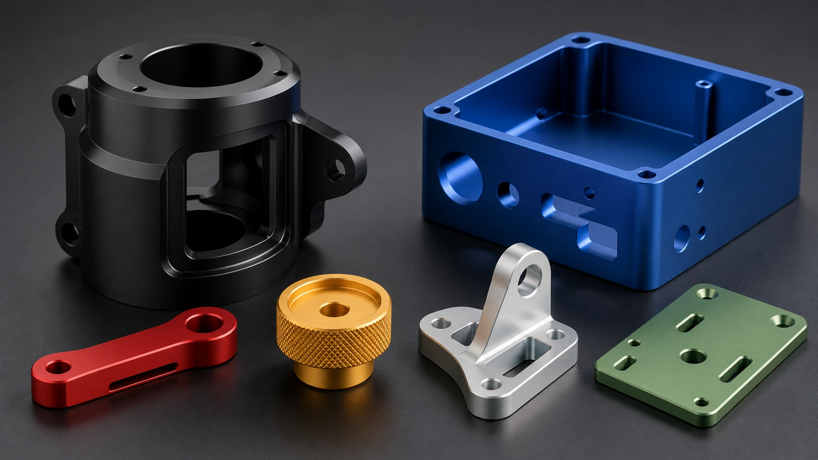
Un guide d'ingénierie pratique pour le type I, Type II, et anodisation de type III, contrôle des couleurs, épaisseur du revêtement, tolérance dimensionnelle, masquage, scellage, inspection, et exigences de dessin.
Introduction
6061-Le T6 est largement utilisé pour les pièces CNC anodisées car il combine un bon comportement d'usinage avec une réponse d'anodisation généralement uniforme.. L'anodisation peut améliorer la résistance à la corrosion, fournir une surface plus dure, créer une couleur décorative, et isoler électriquement les zones sélectionnées. Ces avantages dépendent du choix du bon processus et de sa spécification claire..
La finition doit être planifiée avant l'usinage, pas ajouté après coup. L'épaisseur du revêtement change les dimensions, le prétraitement change l'apparence, chaque pièce a besoin d'un contact de rack, et les couleurs teintes varient selon l'alliage, texture, épaisseur du film, état du bain, et l'étanchéité. JADE-CNC examine ces facteurs dans le cadre de son aide à la finition de surface pour pièces usinées en aluminium.
Pour la relation plus large entre la sélection de l'alliage, usinage, tolérances, finition, et le coût, commencer par le 6061-Guide complet d'usinage CNC en aluminium T6.
Quel est l'effet de l'anodisation sur l'aluminium 6061-T6
L'anodisation est un processus de conversion électrochimique. La pièce en aluminium fait office d'anode dans une cellule électrolytique, et sa surface est transformée en oxyde d'aluminium. Contrairement à la peinture ou au placage, la couche anodique n'est pas simplement déposée sur le métal. Une partie de l'oxyde se forme sous la surface d'origine et une partie se forme vers l'extérieur..
L'oxyde résultant est poreux avant le scellement. Ces pores rendent possible la teinture décorative, mais cela signifie également que l'étanchéité et le traitement final doivent correspondre au service prévu. Un revêtement décoratif scellé, un revêtement dur non scellé pour des performances d'abrasion maximales, et une interface électrique masquée sont trois spécifications techniques différentes.
Séquence de processus typique
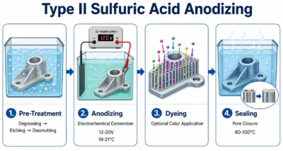
- Nettoyer la pièce et éliminer les fluides d'usinage, empreintes digitales, et résidus.
- Appliquer le prétraitement mécanique ou chimique requis.
- Rackez la pièce pour fournir un contact électrique et soutenir le drainage.
- Anodiser selon le type et l'épaisseur de revêtement spécifiés.
- Colorer le film poreux lorsqu'une finition teinte ou colorée par électrolyse est requise.
- Scellez le revêtement lorsque les spécifications et les conditions de service nécessitent un scellement.
- Inspecter l'apparence, épaisseur, dimensions, fils de discussion, masquage, et tous les tests de performances spécifiés.
Scène | Ce qui se produit | Ce que les ingénieurs devraient contrôler |
Nettoyage | Huile, liquide de refroidissement, empreintes digitales, et les résidus d'atelier sont éliminés | Trous borgnes, fluide emprisonné, inserts, et contamination |
Prétraitement | Gravure, démoulage, dynamitage, brossage, ou le polissage établit la surface | Visages cosmétiques, texture, uniformité des stocks, et état des bords |
Rayonnage | Le contact électrique transporte le courant et soutient la pièce | Emplacement du marquage du rack, drainage, orientation, et zone de contact |
Anodisation | La surface de l'aluminium se transforme en oxyde d'aluminium poreux | Type de revêtement, épaisseur, alliage, répartition actuelle, et contrôle du bain |
Coloration | Un colorant ou une coloration électrolytique est appliqué lorsque spécifié | Échantillon approuvé, gamme de couleurs, épaisseur du film, et la cohérence des lots |
Scellage | Les pores sont fermés pour améliorer la corrosion et la rétention de la couleur | Méthode de scellement, exigences d'usure, stabilité du colorant, et spécification régissant |
Inspection | Apparence, épaisseur, dimensions, fils de discussion, et les tests spécifiés sont vérifiés | Critères d'acceptation et lieux de tests définis avant la production |
Tapez I, Type II, et anodisation de type III
Le Type I familier, II, et les étiquettes III proviennent de MIL-PRF-8625. La spécification inclut également des sous-types supplémentaires et sépare la classe 1 revêtements, qui ne sont pas intentionnellement teints, de la classe 2 revêtements, qui sont teints ou pigmentés. Un dessin doit nommer la norme applicable, taper, classe, épaisseur, couleur, scellage, masquage, et les tests requis au lieu de s'appuyer sur le mot « anodiser »’ seul.
Type d'anodisation | Famille de processus | Plage d'épaisseur commune | Raison typique pour le préciser |
Tapez I | Acide chromique | Mince, souvent à propos 0.5-7.5 un | Spécifications aérospatiales ou héritées; pièces complexes et sensibles à la fatigue |
Type II | Acide sulfurique | Souvent 5-25 un | Couleur décorative, protection contre la corrosion, et pièces CNC générales |
Type III | Anodisation sulfurique dure | Souvent 25-50 un; des plages plus larges sont possibles | Résistance à l'usure, surfaces plus dures, et pièces d'ingénierie fonctionnelle |
Les gammes sont des références pratiques, pas de limites universelles. Le dessin directeur et les spécifications contrôlent l’exigence finale.
Tapez I: Anodisation à l'acide chromique
Le type I produit un revêtement relativement fin et a une longue histoire dans les applications aérospatiales, y compris des formes complexes et certaines pièces sensibles à la fatigue. Parce que la chimie traditionnelle de type I utilise du chrome hexavalent, les exigences environnementales et réglementaires doivent être revues. Des alternatives non chromées de type IC existent sous MIL-PRF-8625, mais ils ne devraient pas être considérés comme automatiquement interchangeables avec le type I sans approbation.
Type II: Anodisation à l'acide sulfurique
Le type II est le choix habituel pour les pièces décoratives et protectrices 6061-T6. Il prend en charge les finitions claires ou naturelles et une large gamme de colorants, tout en offrant une résistance utile à la corrosion et à la manipulation. L'épaisseur du film est généralement sélectionnée en fonction de l'exposition en service, apparence, tolérance dimensionnelle, et la spécification applicable plutôt que par la couleur seule.
Type III: Anodisation dure
Le type III utilise un contrôle plus strict de la température et du courant pour construire un, revêtement plus dur pour des surfaces fonctionnelles résistantes à l'usure. Le revêtement naturel peut paraître gris, bronze, brun, ou presque noir selon l'alliage et l'épaisseur. Des colorants foncés peuvent être possibles, mais les couleurs cosmétiques vives ne constituent pas une attente fiable en matière de revêtement dur. L'étanchéité dépend du service car elle peut améliorer le comportement à la corrosion tout en modifiant les performances à l'abrasion..
Contrôle de processus de type II
Nettoyage, Gravure, et démoulage
Le nettoyage élimine l'huile et la contamination de l'atelier. Une gravure alcaline peut réduire les variations visuelles mineures et créer une surface mate, mais cela enlève également de la matière et peut adoucir les bords ou modifier les dimensions. Le démoulage élimine les résidus d’éléments d’alliage laissés après la gravure. La chimie exacte, température, et le temps sont spécifiques au processeur et doivent être validés pour l'alliage, géométrie de la pièce, et l'apparence souhaitée.
Soutirage et distribution de courant
Le rayonnage est une décision à la fois électrique et esthétique. Le point de contact laissera une marque de rack, et la densité de courant peut se concentrer sur les bords, fils de discussion, ou de fines projections. Identifiez un emplacement de rack acceptable sur les pièces d'apparence critique et permettez le drainage des éléments aveugles.. Grandes surfaces, poches profondes, et les pièces densément imbriquées peuvent nécessiter une orientation spéciale ou des contacts auxiliaires.
Teinture et scellement
La couleur du colorant dépend de la structure des pores, épaisseur du revêtement, concentration de colorant, état du bain, temps d'immersion, et la surface sous le revêtement. Le scellement ferme ou modifie les pores pour améliorer la résistance à la corrosion et conserver la couleur. Les méthodes courantes incluent l'eau chaude, acétate de nickel, et scellement chimique à basse température, mais les spécifications applicables et les exigences de performance devraient déterminer la méthode.
Épaisseur du revêtement et changement dimensionnel
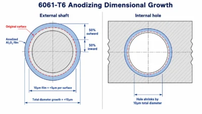
Le commun 50/50 la règle est utile pour les premiers DFM: environ la moitié de l'épaisseur de l'oxyde est traitée comme une accumulation vers l'extérieur et l'autre moitié comme une pénétration dans la surface d'origine. C'est une estimation, pas un facteur de conversion universel. Alliage, type d'anodisation, épaisseur, contrôle du bain, prétraitement, et la pratique du processeur peut changer la relation, spécialement pour l'anodisation dure.
Revêtement spécifié | Estimation de conception commune | Effet de diamètre approximatif | Remarque importante |
10 euh Type II | À propos 5 um croissance vers l'extérieur par surface | +10 euh sur un arbre; -10 euh, c'est ennuyeux | Vérifier le taux de croissance avec le processeur |
20 euh Type II | À propos 10 um croissance vers l'extérieur par surface | +20 euh sur un arbre; -20 euh, c'est ennuyeux | Peut affecter les ajustements, fils de discussion, et sièges de roulement |
25 euh Type III | À propos 12.5 um croissance vers l'extérieur par surface | +25 euh sur un arbre; -25 euh, c'est ennuyeux | L'accumulation réelle peut varier selon le processus de revêtement dur. |
50 euh Type III | À propos 25 um croissance vers l'extérieur par surface | +50 euh sur un arbre; -50 euh, c'est ennuyeux | Utiliser les allocations confirmées par le processeur sur les fonctionnalités de précision |
Les exemples de conception approximatifs supposent 50% accumulation vers l'extérieur. Confirmer la surépaisseur d'usinage finale avec la source d'anodisation sélectionnée.
Arbres, Alésages, Machines à sous, et convient
Si un 10 euh, le revêtement produit environ 5 um de croissance vers l'extérieur par surface, un diamètre externe augmente d'environ 10 euh et un diamètre interne rétrécit d'environ 10 un. C'est pourquoi les sièges de roulement, trous de cheville, diamètres d'étanchéité, fentes de précision, et les ajustements à la presse doivent être dimensionnés pour l'état fini et revus pendant usinage CNC sur mesure.
Sujets
La stratégie de thread dépend de la fonction. Le masquage préserve l'ajustement d'origine et la conductivité nue mais laisse le fil sans protection. La surépaisseur d'usinage peut garder le filetage recouvert, mais cela nécessite un accord sur l'accumulation du revêtement. La poursuite de l'anodisation rétablit l'ajustement mais élimine une partie ou la totalité de l'oxyde des flancs du filetage.. Indiquez la méthode prévue sur le dessin au lieu de la laisser à l'interprétation de la production..
Options de couleur et cohérence des couleurs
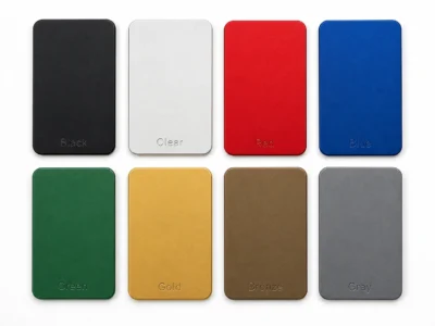
Le type II 6061-T6 peut être produit en naturel ou transparent, noir, bleu, rouge, vert, or, bronze, gris, et autres systèmes de teinture proposés par le transformateur. « Anodisation claire’ n'est pas incolore au sens optique: chimie des alliages, épaisseur du film, prétraitement, et le scellement peut modifier le ton gris ou argenté final.
Une correspondance exacte des couleurs Pantone ou de l'écran ne doit pas être promise sans des échantillons d'approbation physique et une méthode de mesure définie. Le métal anodisé est réfléchissant et directionnel, donc la couleur perçue change avec le brillant, texture, angle de vision, et l'éclairage. Pour les assemblées, utiliser le même alliage et la même source d'origine lorsque cela est possible, usiner les surfaces de manière cohérente, et finition des pièces visibles en un seul lot contrôlé.
La chimie de l'alliage et l'état du stock influencent à la fois la résistance et la réponse de finition. Le 6061-Guide des propriétés de l'aluminium T6 fournit les informations mécaniques pertinentes, thermique, et données chimiques. Lorsqu’une résistance plus élevée est envisagée, la publication 6061-Comparaison de l'aluminium T6 et 7075-T6 explique les différences d'usinabilité associées, coût, comportement à la corrosion, et attentes en matière d'anodisation.
Spécifier l'apparence avec des échantillons et des tolérances
- Identifier les visages cosmétiques et l'emplacement acceptable des marques de rack.
- Définir le prétraitement: comme usiné, microbillé, brossé, brillant, ou une autre texture contrôlée.
- Utilisez un échantillon physique ou une gamme de couleurs approuvés pour les travaux critiques en termes d'apparence..
- Si un contrôle instrumental des couleurs est requis, définir l'espace colorimétrique, illuminant, géométrie, état de brillance, et tolérance d'acceptation.
- Conserver l'alliage, caractère, préparation des surfaces, épaisseur du revêtement, colorant, et joint cohérent entre les pièces de comparaison.
Préparation de surface avant l'anodisation
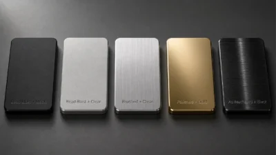
L'anodisation suit le métal sous-jacent; il ne cache pas les rayures, ondulation, bosses, ou parcours d'outils incohérents. La préparation de la surface doit donc faire partie du parcours d'usinage et de finition.. JADE-CNC peut revoir la transition de usinage CNC en aluminium au dynamitage, brossage, polissage, et anodisation avant le début de la production.
État pré-anodisé | Résultat visuel typique | Principal avantage | Risque principal |
Comme usiné | Les parcours d'outils restent visibles | Préparation ajoutée la plus faible | Les marques d'usinage et les différences de texture locales restent visibles |
Microbillé | Aspect mat uniforme | Réduit l'accent visuel sur les parcours d'outils | Médias, pression, manutention, et la variation de l'alliage affecte la cohérence |
Brossé | Grain linéaire directionnel | Texture décorative maîtrisée | La direction du grain et les transitions des bords doivent être cohérentes |
Brillant | Finition brillante ou réfléchissante | Aspect décoratif haut de gamme | Toute rayure ou ondulation reste visible après anodisation |
Dégringolé | Finition mate douce avec bords adoucis | Efficace pour les petites pièces adaptées | Peut modifier les bords, petites fonctionnalités, et détails dimensionnels |
Pour les pièces critiques en termes d'apparence, spécifier la rugosité de la surface uniquement lorsque cela est fonctionnellement utile. Une valeur numérique Ra ne décrit pas complètement un grain brossé, texture explosive, ou brillant visuel. Échantillons de processus et contrôlés Fraisage CNC les stratégies fournissent souvent de meilleurs conseils en matière d’apparence.
Marques d'outils, bavures, et le mouvement des parois minces doit être contrôlé avant la finition. Utilisez le 6061-Guide des paramètres d'usinage CNC T6 revoir l'outillage, vitesses, se nourrit, évacuation des copeaux, et stratégie de passe de finition avant anodisation.
Masquage, Insertions, et interfaces d'assemblage
Le masquage est utilisé là où le contact électrique, ajustement précis, collage, mise à la terre, scellage, ou l'assemblage nécessite de l'aluminium nu. Les méthodes courantes incluent les fiches, casquettes, bandes, et masques réutilisables. Chaque limite masquée a une tolérance de processus, le dessin doit donc identifier à la fois la zone fonctionnelle et la zone de transition acceptable.
- Patins de mise à la terre et surfaces de contact EMI
- Sièges de roulement, trous de cheville, alésages de précision, et phoque des terres
- Filets et inserts filetés sélectionnés
- Interfaces de connecteurs électriques
- Zones réservées au soudage, liaison, ou usinage ultérieur
- Surfaces de référence ou de contact sur lesquelles l'accumulation de revêtement n'est pas autorisée
Inserts en acier, hélicoptères, aimants, et d'autres matériaux différents sont généralement plus faciles à contrôler lorsqu'ils sont installés après anodisation. S'ils doivent être présents au préalable, le transformateur doit examiner la compatibilité chimique, masquage, solution piégée, et risque galvanique.
Règles de conception pour les pièces anodisées 6061-T6
Zone de conception | Dessin recommandé ou action DFM | Raison |
Ajustements précis | Définir les dimensions finales après finition et confirmer la tolérance de revêtement | La croissance anodique change les arbres, alésages, machines à sous, et les espaces d'accouplement |
Sujets | Choisissez parmi le masquage, allocation, ou après la poursuite et énoncer le choix | Le chassage rétablit l'ajustement mais enlève le revêtement des surfaces de filetage |
Surfaces de mise à la terre | Marquez les zones sans anodisation et définissez la zone de contact acceptable | L'oxyde anodique est électriquement isolant |
Marques de crémaillère | Identifier les emplacements de contact non cosmétiques | Chaque pièce anodisée a besoin d'un point de contact électrique |
Trous borgnes | Assurer le drainage lorsque cela est possible et signaler les risques de solutions piégées | Les produits chimiques retenus peuvent tacher ou endommager la pièce |
Arêtes vives | Utilisez des rayons ou des chanfreins pratiques et examinez la densité de courant de la couche dure | Le revêtement peut être mince, fragile, ou brûlé sur les bords difficiles |
Métaux mixtes | Installer des inserts en acier et du matériel différent après l'anodisation lorsque cela est possible | Empêche la contamination du bain, attaque, et solution piégée |
Assemblages cosmétiques | Terminer les pièces à assembler dans le même lot contrôlé | Réduit la variation de couleur visible entre les composants assemblés |
La traçabilité des matériaux compte également pour l'apparence. Différent 6061 les formes de produits et les fournisseurs peuvent réagir différemment même lorsque la désignation de l'alliage est la même. Le Guide des matériaux d'usinage CNC fournit un point de départ utile, mais le bon de commande doit quand même définir la forme de stock requise, caractère, et certification.
La marge de revêtement doit être coordonnée avec l'épaisseur du mur, convient, trous, fils de discussion, rayons, et allocation de tolérance. Le 6061-Directives DFM pour l'usinage CNC T6 regrouper ces décisions de conception dans une seule liste de contrôle de fabrication.
Comment spécifier l'anodisation sur un dessin technique
Une note d'anodisation utilisable indique au transformateur ce qu'il doit faire et comment l'acceptation sera jugée. Évitez les notes telles que « anodisation noire »’ sans type, épaisseur, ou informations de masquage.
Informations minimales sur le dessin
- Norme applicable et révision, lorsque requis
- Type d'anodisation et désignation de classe ou de couleur
- Épaisseur de revêtement ou plage d'épaisseur requise
- État scellé ou non scellé et toute méthode de scellement spécifiée
- Prétraitement ou texture de surface requise
- Zones masquées et non anodisées, y compris la tolérance de la zone de transition
- Restrictions d'emplacement de marquage de rack
- Dimensions et tolérances applicables après finition
- Échantillon d'apparence, tolérance de couleur, ou condition de visualisation contrôlée
- Inspections et tests de performance requis
Exemple de note de dessin
Exemple: Anodisation selon MIL-PRF-8625, Type II, Classe 2, noir, 10-15 un; scellé. Masquer les plots de mise à la terre et les filetages M4 identifiés. Les dimensions s'appliquent après la finition. Marques de rack autorisées uniquement sur la face non cosmétique marquée. Couleur conforme à l'échantillon de production approuvé.
L'exemple est volontairement spécifique, mais ce n'est pas une exigence universelle. Ajuster la norme, épaisseur, scellage, couleur, et tests à l'état de service réel.
Inspection et dépannage
Plan d'inspection
L'inspection doit suivre le risque de dessin. Les contrôles typiques incluent l'apparence visuelle sous un éclairage contrôlé, épaisseur du revêtement aux endroits convenus, dimensions post-finition, jaugeage de filetage, masquage des limites, et tests d'étanchéité ou de corrosion lorsque spécifié. JADE-CNC peut coordonner ces contrôles à travers ses Services d'inspection CNC.
- Mesurer l'épaisseur sur accessible, zones représentatives et enregistrer la méthode.
- Jaugez les filetages et les ajustements critiques après la finition.
- Inspecter la couleur et la texture par rapport à l'échantillon approuvé sous un éclairage défini.
- Utilisez les tests au brouillard salin uniquement avec une méthode de test nommée, durée, préparation des échantillons, état d'étanchéité, et critère d'acceptation.
- Examinez la qualité du joint lorsque la résistance à la corrosion ou la rétention du colorant sont critiques.
Défauts courants et causes probables
- Variation de couleur: Stock mixte, texture incohérente, variation de l'épaisseur du film, état du colorant, scellage, ou séparation des lots.
- Taches ou taches blanches: Mauvais rinçage, chimie piégée, qualité de l'eau, manutention, ou problèmes d'étanchéité.
- Saignement de colorant: Étanchéité insuffisante ou post-nettoyage incompatible.
- Bords brûlés: Densité de courant locale excessive, géométrie, mauvais contact, ou refroidissement inadéquat.
- Apparence inégale: Contamination, prétraitement inégal, variation d'alliage, ou des dommages superficiels.
- Filetages ou alésages serrés: La tolérance de revêtement ou la stratégie de masquage n'a pas été définie.
- Marques de rack sur les visages cosmétiques: Le lieu de contact n'a pas été convenu avant le traitement.
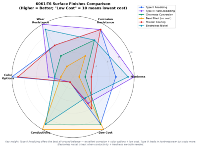
Anodisation comparée à d'autres finitions
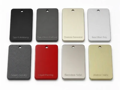
Finition | Le mieux adapté à | Comportement électrique | Limite clé |
Anodisation de type II | Protection contre la corrosion et couleur décorative | Isolant | La couleur et l'épaisseur nécessitent un contrôle du processus |
Anodisation de type III | Surfaces fonctionnelles résistantes à l'usure | Isolant | Accumulation plus épaisse et gamme de couleurs cosmétiques limitée |
Revêtement de conversion chimique | Protection contre la corrosion et contact électrique | Plus conducteur que l'anodisation | L'apparence et la chimie dépendent du système spécifié |
Revêtement en poudre | Décoration épaisse et protection de l'environnement | Isolant | Plus grande épaisseur et précision dimensionnelle inférieure |
Nickel chimique | Porter, conductivité, et barrière de protection | Conducteur | Coût plus élevé et mode de défaillance différent de l'anodisation |
Nu ou microbillé | Apparition temporaire ou usage intérieur contrôlé | Conducteur | Résistance limitée à la corrosion et aux taches |
L'anodisation est souvent la meilleure solution lorsque le substrat est en aluminium et que le projet nécessite une résistance à la corrosion., faible poids ajouté, aspect contrôlé, ou une surface dure. Ce n'est pas la bonne réponse lorsqu'une interface doit rester conductrice, une couche décorative très épaisse est nécessaire, ou un revêtement barrière est préféré à une surface d'oxyde convertie.
Le choix de la finition dépend également du parcours de fabrication. Pour les pièces de plus grand volume où le moulage sous pression peut remplacer l'usinage à partir de tôles ou de barres forgées, le 6061-Comparaison de l'aluminium T6 et ADC12 couvre l’investissement en outillage, coût unitaire, propriétés, tolérances, porosité, et les compromis de finition.
Facteurs de coût et de délai
Le coût de l'anodisation dépend généralement des frais de lot minimaux, taille de la pièce, superficie totale, difficulté de soutirage, masquage, prétraitement, couleur, épaisseur, scellage, inspection, et rejeter le risque. Les prix fixes par pièce ou les multiplicateurs universels de type III ne sont pas fiables sans dessin et quantité..
Pour les prototypes et usinage CNC à faible volume, les échantillons de couleur et l'inspection du premier article peuvent prolonger le temps mais réduire le risque qu'un lot complet soit visuellement ou dimensionnellement inacceptable. Devis usinage et finition ensemble lorsque cela est possible donc masquage, allocation, et l'inspection sont inclus dans un seul plan de processus.
Comment JADE-CNC prend en charge les pièces en aluminium anodisé
JADE-CNC prend en charge la coordination de l'usinage CNC et de l'anodisation pour 6061 et autres alliages d'aluminium. L'examen commence par le dessin et le service prévu, puis relie l'état du matériau, surépaisseur d'usinage, préparation cosmétique, masquage, exigences de finition, et inspection finale. C'est plus fiable que de traiter l'anodisation comme un achat séparé une fois que la pièce est déjà usinée..
- Examen de l'alliage, caractère, formulaire de stock, et finition compatibilité
- DFM pour l'accumulation de revêtement, convient, fils de discussion, parois minces, emplacements des racks, et drainage
- Coordination du brut d'usinage, microbillé, brossé, brillant, et surfaces anodisées
- Options d'anodisation de type II et de type III soumises à l'examen des dessins et du projet
- Examen du masquage des plots de mise à la terre, fils de discussion, alésages, et interfaces d'assemblage
- Dimensionnelle post-finition, fil, apparence, et inspection de l'épaisseur selon les besoins
- Échantillonnage de prototypes et planification des lots de production
Envoyer le modèle CAO, 2Dessin D, quantité, alliage, note d'anodisation, exigences cosmétiques, et environnement de service à JADE-CNC pour demander une revue de finition et d'usinage.
Foire aux questions
Questions d'ingénierie courantes
Le 6061-T6 s'anodise-t-il bien?
Oui. 6061-T6 donne généralement une réponse d'anodisation décorative et protectrice uniforme. L'aspect final dépend toujours de la consistance du stock, prétraitement, épaisseur du film, colorant, scellage, et manipulation.
Dans quelle mesure l'anodisation change-t-elle les dimensions?
Une première estimation courante suppose qu'environ la moitié de l'épaisseur du revêtement se développe vers l'extérieur.. Pour un 10 euh revêtement, cela suggère environ 5 um croissance par surface. Confirmer l'allocation réelle auprès du processeur, spécialement pour le type III.
Les trous filetés doivent-ils être masqués?
Cela dépend de la corrosion, conductivité, classe de fil, épaisseur du revêtement, et besoins d'assemblage. Masquage, surépaisseur d'usinage, et la poursuite après l'arrivée comportent chacune des compromis qui doivent être indiqués sur le dessin..
Peut anodisé 6061 correspondre à une couleur Pantone exacte?
Une cible visuelle proche peut être possible, mais la correspondance exacte entre les matériaux est difficile car le métal anodisé est réfléchissant et dépend de la texture. Utiliser un échantillon d'approbation physique et une méthode d'acceptation définie.
Peut soudé 6061 les assemblages soient anodisés?
Oui, mais le métal soudé et les zones affectées par la chaleur peuvent présenter une teinte différente. Alliage de remplissage, mélange de soudure, prétraitement, et l'approbation des échantillons doit être revue pour les travaux cosmétiques.
L'anodisation dure est-elle toujours scellée?
Non. L'étanchéité dépend des spécifications et du service. Il peut améliorer les performances en matière de corrosion mais peut modifier le comportement à l'abrasion., les dessins de revêtement dur doivent donc indiquer l'état requis.
Combien de temps prend l'anodisation?
Le délai dépend de la planification des lots, couleur, masquage, épaisseur, échantillonnage, inspection, et risque de reprise. Confirmez-le lors du devis plutôt que de vous fier à un numéro universel.
Conclusion
Le type II est le choix habituel pour les pièces décoratives et protectrices 6061-T6, tandis que le type III est utilisé lorsque la résistance à l'usure et un revêtement technique plus épais sont plus importants qu'une couleur vive.. Le type I reste pertinent lorsqu'une spécification aérospatiale ou existante à base d'acide chromique l'exige. Le bon choix dépend de la fonction, environnement, dimensions, apparence, et la norme en vigueur.
L'étape de conception la plus importante consiste à définir l'anodisation avant de finaliser le plan d'usinage.. Précisez le type, épaisseur, couleur ou classe, scellage, prétraitement, masquage, restrictions relatives aux marques de crémaillère, dimensions finales après finition, et tests d'acceptation. Cela transforme l'anodisation d'une demande cosmétique en une exigence de fabrication contrôlable..
Articles connexes sur le 6061-T6
- 6061-Guide complet d'usinage CNC en aluminium T6
- 6061-T6 contre aluminium 7075-T6: Force, Coût & Usinabilité
- 6061-Anodisation de l'aluminium T6: Espèces, Couleurs, Épaisseur & Règles de conception
- 6061-Paramètres d'usinage CNC T6: Vitesses, Flux, Outillage & Contrôle des processus
- 6061-T6 contre ADC12 Aluminium: Usinage CNC ou moulage sous pression?
- 6061-Directives DFM pour l'usinage CNC T6: Règles de conception & Liste de contrôle
- 6061-Propriétés de l'aluminium T6: Mécanique, Thermique & Données chimiques
Normes référencées
Pour les exigences de dessin et les critères d’acceptation, consulter le cahier des charges actuel du projet. Les références pertinentes incluent MIL-PRF-8625 pour le type I, II, et III classifications militaires; OIN 7599:2018 pour revêtements d'oxydation anodique décoratifs et protecteurs; et OIN 10074:2021 pour revêtements d'oxydation anodique durs. Les dessins du client et les exigences contractuelles prévalent.

Léo Liang, Fondateur Meilleur partenaire avec R&D
LEO, fondateur de JADE-CNC, qui apporte plus de deux décennies d'expertise dans l'industrie, Leo a commencé sa carrière en tant qu'apprenti et met en pratique ses compétences en traitement de surface et en usinage CNC..