


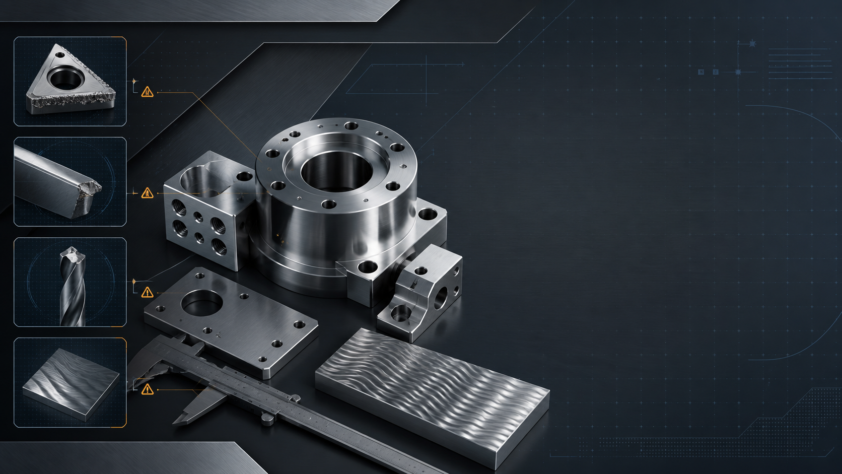
Warum die Bearbeitung von Edelstahl immer wieder Probleme bereitet
Edelstahl ist eines der frustrierendsten Materialien bei der CNC-Bearbeitung. Auf derselben Maschine mit demselben Werkzeug, Aluminium schneidet reibungslos, aber wechseln zu 304 oder 316 bringt Aufbaukante, verbrannte Werkzeuge, kaputte Bohrer, und Rattermarken auf der Oberfläche. Viele Ingenieure führen dies darauf zurück “Edelstahl ist schwer zu bearbeiten,” aber wenn man genau fragt, warum und wie man das Problem beheben kann, Die Antworten sind oft vage.
Die Schwierigkeit lässt sich auf drei Hauptursachen zurückführen. Erste, starke Verfestigungstendenz – Die bearbeitete Oberfläche bildet eine gehärtete Schicht, die härter ist als das Grundmaterial, und wenn der nächste Schnitt auf dieser gehärteten Schicht verläuft, Der Werkzeugverschleiß nimmt dramatisch zu. Zweite, hohe Warmfestigkeit – Die Schneidzone erreicht hohe Temperaturen, das Material erweicht jedoch nicht, Daher ist das Werkzeug thermisch stark belastet. Dritte, hohe Duktilität und Haftung – Späne neigen dazu, an der Schneidkante zu verschweißen, Es bilden sich Aufbauschneiden, die die Oberflächenbeschaffenheit und Maßhaltigkeit beeinträchtigen.
In diesem Artikel werden die vier häufigsten Probleme bei der CNC-Bearbeitung von Edelstahl beschrieben – Aufbaukante, Werkzeugverschleiß, kaputte Bohrer, und Geschwätz – und für jeden, teilt die Lösungen, die wir in der tatsächlichen Produktion validiert haben, zusammen mit der Art und Weise, wie wir diese Lösungen in Fabrikabläufe standardisieren. Für das breitere Material, Abschluss, Inspektion, und Lieferantenauswahlpfad, Beginnen Sie mit dem CNC-Bearbeitungsanleitung aus Edelstahl.
Aufbaukante: Der versteckte Killer der Oberflächenbeschaffenheit
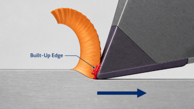
Aufbauschneidenbildung ist das häufigste, aber am meisten übersehene Problem bei der Bearbeitung von Edelstahl. Beim Schneiden, Das darunter liegende Metall des Spans haftet unter hohem Druck und hoher Temperatur an der Schneidkante, ein wachsendes bilden “Rand” die die eigentliche Werkzeugschneide ersetzt. Dieses BUE schneidet anstelle des Werkzeugs, Dies führt zu einer schnellen Verschlechterung der Oberflächenbeschaffenheit, Dimensionen zum Driften, und in schweren Fällen, Das BUE löst sich und nimmt Werkzeugmaterial mit, zu Absplitterungen führen.
So identifizieren Sie aufgebaute Kanten
Unregelmäßige Kratzer und Risse auf der bearbeiteten Oberfläche, Dimensionen, die unvorhersehbar schwanken, und sichtbare Materialanhaftungen an der Spanfläche des Werkzeugs sind typische Anzeichen. Viele Bediener gehen davon aus, dass das Werkzeug langweilig ist oder die Parameter falsch sind, das Werkzeug wechseln, und sehe das gleiche Problem – Das ist aufgebaute Kante am Werk.
Lösung: Kontrolltemperatur, Haftung, und Spanfluss
Die Bildung von BUE hängt von der Schnitttemperatur und der Materialhaftung ab. Unser Ansatz ist die Temperaturkontrolle, Haftung reduzieren, und unterdrücken Sie BUE von der Quelle durch eine Kombination aus Werkzeugen und Parametern. Zur Schnittgeschwindigkeit, im mittleren bis niedrigen Bereich (Vc 30-60 m/min) Hier bildet sich BUE am leichtesten. Normalerweise erhöhen wir die Geschwindigkeit auf Vc 80-120 m/min – Die Schnitttemperatur steigt, aber der Spanfluss beschleunigt sich, wodurch eine Haftung weniger wahrscheinlich wird. Natürlich, Eine zu hohe Geschwindigkeit beschleunigt den Werkzeugverschleiß, Das Gleichgewicht hängt also vom jeweiligen Material und Werkzeug ab. Dies ist insbesondere beim Vergleich wichtig 304, 316, und 316L; sehen 304 vs 316 vs. Edelstahl 316L für den Notenauswahlkontext.
Über Werkzeuge, Wir verwenden standardmäßig TiAlN-beschichtete Wendeschneidplatten, die bei hohen Temperaturen ihre Härte behalten und eine glatte Oberfläche haben, die der Adhäsion widersteht. Für die Hochgeschwindigkeitsbearbeitung von 316/316L, Wir wechseln zur AlTiN-Beschichtung. Der Spanwinkel ist gegenüber dem herkömmlichen vergrößert 10 Ihr zwei 15-20 Grad, Reduzierung der Schnittverformung und Verbesserung des Spanflusses. Beim Abkühlen, Bei der Bearbeitung von Edelstahl wird immer Schneidöl mit hohem Durchfluss oder Hochdruckkühlmittel verwendet (70+ Bar), Direkt in die Schneidzone geleitet, um die Temperatur zu senken und die Späne wegzuspülen, Verringerung der Adhäsionsmöglichkeiten. Auch die Vorschubgeschwindigkeit ist wichtig – unten 0.1 mm/r, Das Werkzeug reibt und extrudiert statt zu schneiden, Verschlechterung der Haftung, also halten wir normalerweise 0.15-0.25 mm/r.
Parameter | TAUBEN-anfälliges Setup | Empfohlener Bereich für 304 / 316 |
Schnittgeschwindigkeit Vc | 30-60 m/min | 80-120 m/min |
Werkzeugbeschichtung | Unbeschichtet / Zinn | TiAlN / Gold |
Spanwinkel | 5-10 Grad | 15-20 Grad |
Kühlmittel | Emulsion / Luftstoß | Schneidöl mit hohem Fließvermögen / Hochdruckkühlmittel |
Vorschubgeschwindigkeit | Zu niedrig (<0.1 mm/r) | 0.15-0.25 mm/r |
Fallstudie
Beenden Sie das Ausdrehen 316 Die Dichtflächen des Ventilkörpers aus Edelstahl sind ein Szenario mit hohem BUE-Wert. Wir hatten einmal eine Charge, bei der die fertiggedrehte Oberfläche unregelmäßige Kratzer aufwies, mit Ra, der vom Erforderlichen springt 0.8 ähm zu 1.6-3.2 ähm und dimensionale Ablehnung herum 15%. Die Inspektion ergab deutliche Materialanhaftungen an der Spanfläche des Werkzeugs, Bestätigung der Aufbaukante. Die damaligen Parameter waren Vc=50 m/min und Vorschub 0.08 mm/r – genau im BUE-anfälligen Bereich.
Nach der Anpassung, Schnittgeschwindigkeit erhöht auf Vc=90 m/min, füttern 0.15 mm/r, Werkzeuge auf TiAlN-beschichtete Wendeschneidplatten umgestellt 15 Sie neigen den Winkel, und das Kühlmittel wurde auf Schneidöl mit hohem Durchfluss umgestellt. Oberflächenbeschaffenheit unter Ra stabilisiert 0.8 eins, Die dimensionale Ablehnung fiel darunter 1%, und die Standzeit verbesserte sich von 30 Zu 65 Teile. Diese Anpassung wurde später in unserem Parametersatz für das Fertigdrehen von Edelstahl standardisiert.
JADE-CNC-Standardisierungsprozess
Beim Schlichtdrehen von rostfreiem Stahl werden einheitlich TiAlN-beschichtete Wendeschneidplatten verwendet 15-20 Sie neigen den Winkel; Schnittgeschwindigkeit auf Vc geregelt 80-120 m/min, Füttern Sie nicht weniger als 0.15 mm/r; Als Kühlmittel muss Schneidöl mit hohem Durchfluss oder Hochdruckkühlmittel verwendet werden. Der Schwerpunkt der Erstmusterprüfung liegt auf der Oberflächenbeschaffenheit und der Spanflächenhaftung; Das erkannte BUE löst eine sofortige Parameteranpassung aus. Die Werkzeuglebensdauer wird pro Charge aufgezeichnet, um Standards für die Werkzeuglebensdauer beim Fertigdrehen von Edelstahl festzulegen. Dieser Prozess stimmt mit JADE-CNCs überein CNC-Drehen Fähigkeit.
Werkzeugverschleiß: Der Produktionskostentreiber
Werkzeugverschleiß ist das direkteste Kostenproblem bei der Bearbeitung von Edelstahl. Ein Einsatz kann produzieren 80 Teile drin 304, aber nur 40-45 In 316, und noch weniger in 316L. Werkzeugkosten plus Werkzeugwechselzeit summieren sich zu einer erheblichen Lücke in der Serienproduktion.
Drei Hauptverschleißmuster bei Edelstahl
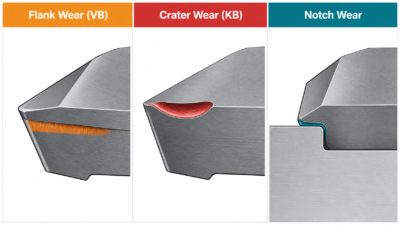
Flankenverschleiß (VB) ist am häufigsten – Auf der Werkzeugflanke bildet sich nach und nach ein Verschleißband, und sobald es überschritten wird 0.3 mm, Oberflächenqualität und Dimensionsstabilität beginnen sich zu verschlechtern. Kraterverschleiß (KB) erscheint auf der Spanfläche als konkave Vertiefung, die durch Spanreibung abgenutzt wird, häufig bei der Hochgeschwindigkeitsbearbeitung von 316; wenn der Krater tiefer wird, Die Kantenfestigkeit nimmt ab und es kann zu Absplitterungen kommen. Kerbverschleiß entsteht an der Kontaktgrenze zwischen Werkzeug und Werkstück als Rille, häufig bei 316/316L, das zur Kaltverfestigung neigt, Dies führt zu Graten und Kratzern auf der Oberfläche.
Tragemuster | Hauptursache | Lösung |
Flankenverschleiß (VB) | Kaltverfestigung, hohe Temperatur | DOC erhöhen, Gleichlauffräsen, TiAlN-Beschichtung, volles Kühlmittel |
Kraterverschleiß (KB) | Hochgeschwindigkeits-Hochtemperaturschneiden, Spanreibung | Vc reduzieren, AlTiN-Beschichtung, Rechen erhöhen, Hochdruckkühlmittel |
Kerbverschleiß | Grenzverfestigung, insbesondere 316/316L | Werkzeugpfad ändern, DOC erhöhen, Ziehen Sie Cermet-Einsätze in Betracht |
Lösung: Reduzieren Sie den Aufprall der gehärteten Schicht und die Schnitttemperatur
Die Hauptursachen für Werkzeugverschleiß sind Kaltverfestigung und hohe Temperaturen. Wir gehen dies aus drei Richtungen an: Reduzierung des Aufpralls auf die gehärtete Schicht, Senkung der Schnitttemperatur, und Auswahl des richtigen Werkzeugmaterials. Die Schnitttiefe ist der kritischste Faktor – Die kaltverfestigte Edelstahlschicht ist grob 0.1-0.3 mm tief. Wenn der Schnitt zu flach ist, Das Werkzeug reibt ständig an der gehärteten Schicht und verschleißt extrem schnell. Wir nutzen zumindest 1 mm Tiefe beim Schruppen, Stellen Sie auch bei der Endbearbeitung sicher, dass der Schnitt über die Tiefe der gehärteten Schicht hinausgeht, damit das Werkzeug in ungehärtetes Grundmaterial schneidet.
Beim Fräsen, Wir verwenden einheitlich Gleichlauffräsen – Das Werkzeug dringt mit einem dicken Span ein, Vermeiden Sie ein Reiben an der ausgehärteten Schicht, Reduzierung der Kaltverfestigung und des Werkzeugverschleißes. Beim herkömmlichen Fräsen reibt und extrudiert das Werkzeug zunächst die Oberfläche, Verschlechterung der Verhärtung, Deshalb vermeiden wir es bei Edelstahl. Auf Werkzeugmaterial, Standard-Edelstahl verwendet Hartmetall mit TiAlN-Beschichtung; für Hochgeschwindigkeits-316/316L oder sehr große Chargen, Wir berücksichtigen Cermet-Einsätze oder PCBN. Zur Temperaturregelung, die Schneidzone hinein 316 erreichen kann 800-1000 du C, wo die Werkzeughärte stark abnimmt. Kühlmittel mit hohem Durchfluss, entsprechend reduzierte Schnittgeschwindigkeit, und erhöhte Span- und Freiwinkel zur Reduzierung der Reibung tragen alle dazu bei, die Temperatur effektiv zu senken. Für hochfeste rostfreie Güten, Die 17-4Bearbeitung von PH-Edelstahl Der Artikel befasst sich mit der Wärmebehandlung und der Endbearbeitungsplanung.
Fallstudie
Das Außenfräsen langer 316L-Wellen ist ein typisches Werkzeugverschleißszenario. Wir haben einmal eine Charge von 316L-Wellen bearbeitet (40 mm Durchmesser, 300 mm lang) wo Hartmetall-TiN-beschichtete Werkzeuge nur nachträglich gewechselt werden mussten 12 Teile, mit Freiflächenverschleiß VB=0,4 mm und Rattermarken auf der Oberfläche. Die Untersuchung ergab, dass die Schnitttiefe nur gering war 0.5 mm – geringer als die Tiefe der ausgehärteten Schicht – plus konventionelles Fräsen, Vc=60 m/min, und Emulsionskühlmittel. Das Werkzeug arbeitete ständig an der ausgehärteten Schicht, extremen Verschleiß verursachen.
Nach der Anpassung, Schnitttiefe erhöht auf 1.5 mm, auf Gleichlauffräsen umgestellt, Vc erhöht auf 90 m/min, Werkzeuge auf TiAlN-Beschichtung umgestellt, und das Kühlmittel wurde auf Schneidöl mit hohem Durchfluss umgestellt (40 L/min). Standzeit verbessert von 12 Zu 38 Teile, Die Werkzeugkosten pro Teil sanken 68%, Oberflächenbeschaffenheit stabilisiert von Ra 3.2 ähm zu Ra 1.6 eins, und Werkzeugwechselzeit reduziert 65%. Dieser Fall hat uns das bei der Edelstahlbearbeitung klar gemacht, Die Auswahl der Schnitttiefe und des Gleichlauffräsens wirkt sich weitaus stärker auf die Werkzeugstandzeit aus als auf die Werkzeugmarke selbst.
JADE-CNC-Standardisierungsprozess
Beim Edelstahlfräsen wird einheitlich das Gleichlauffräsen eingesetzt; Schruppen DOC nicht weniger als 1 mm, Abschluss-DOC größer als 0.3 mm (Tiefe der ausgehärteten Schicht); Werkzeuge verwenden einheitlich eine TiAlN-Beschichtung, Hochgeschwindigkeits-316/316L verwendet AlTiN oder Cermet; Das Kühlmittel verwendet Schneidöl mit hohem Durchfluss (nicht weniger als 30 L/min). Jeder Arbeitsgang legt einen Standard für die Werkzeuglebensdauer fest – Flankenverschleiß VERB erreichen 0.3 mm löst einen obligatorischen Werkzeugwechsel aus, Warten Sie niemals auf das Absplittern. Die Überprüfung der Werkzeuglebensdauer erfolgt vor der Serienproduktion, Erfassung der tatsächlichen Werkzeugstandzeit pro Material und Arbeitsgang. Siehe JADE-CNCs CNC-Fräsen Seite für entsprechende Bearbeitungsmöglichkeiten.
Kaputte Bohrer: Die Risikozone bei der Tieflochbearbeitung
Beim Bohren in Edelstahl besteht ein hohes Risiko für Bohrerbrüche. Beim Bohren 304/316, Chips sind lang und zäh, nicht leicht brechen, und eine schlechte Spanabfuhr verstopft das Loch, Dadurch steigt das Drehmoment stark an, bis der Bohrer bricht. Ein kaputter Bohrer verschwendet nicht nur den Bohrer, sondern auch das Teil – Ein Bohrer, der in einem tiefen Loch steckt, lässt sich oft nicht entfernen, und das gesamte Teil kann verschrottet werden.
Hauptursachen für Bohrerbrüche
Eine schlechte Spanabfuhr ist die Hauptursache – Edelstahlspäne sind lang und zäh, und die Flötenkapazität ist unzureichend, besonders in tiefen Löchern (Tiefe > 3x Durchmesser). Auch die Kaltverfestigung führt zum Bruch – Ein stumpfer Bohrer schneidet nicht mehr, sondern extrudiert am Lochgrund, Es bildet sich eine gehärtete Schicht, die den nächsten Vorschub härter macht und zu Drehmomentspitzen führt. Eine unzureichende Kühlung führt dazu, dass die Schneidflüssigkeit den Lochboden nicht erreichen kann, so dass der Bohrer überhitzt, erweicht, und verschleißt schneller. Zusätzlich, Standardbohrer haben eine zu lange Meißelschneide, hohe Axialkraft, und schlechte Zentrierung – Alle Faktoren, die dazu beitragen.
Lösung: Tiefbohren, Korrekte Bohrergeometrie, und Kühlmittelzugang
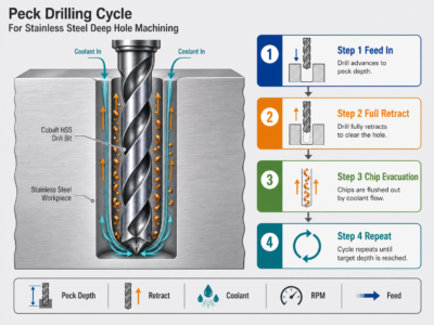
Tieflochbohren ist die einfachste und effektivste Methode zum Bohren von Edelstahl. Wir fahren alle 1-2x Durchmesser zurück, um die Späne abzusaugen, Dadurch kann Schneidflüssigkeit zur Kühlung in den Lochboden eindringen. Für tiefe Löcher (>5x Durchmesser), Tiefbohren ist Pflicht, und der Rückzug muss voll sein – Bei einem teilweisen Rückzug werden die Späne nicht wirklich entfernt. Zur Bohrerauswahl, Wir verwenden einheitlich Kobalt-HSS (HSS-E/Co 5%) oder Hartmetallbohrer mit 135-140 Grad-Punktwinkel (schärfer als der Standard 118 Grad, bessere Zentrierung, geringere Axialkraft), Split-Point-Geometrie zur Reduzierung der Axialkraft, Und 30-35 Grad-Helixwinkel für bessere Spanabfuhr.
Auf Geschwindigkeit und Vorschub, Die Bohrgeschwindigkeit bei Edelstahl sollte nicht zu hoch sein – 304 bei Vc 20-30 m/min, 316/316L bei Vc 15-25 m/min, füttern 0.05-0.12 mm/r. Eine zu hohe Drehzahl verschleißt den Bohrer schnell; Ein zu hoher Vorschub erhöht die Bruchgefahr. Beim Abkühlen, Wo möglich verwenden wir Bohrer mit Innenkühlung, Dabei wird Flüssigkeit durch interne Kanäle direkt zum Lochboden geleitet – Kühlung und Spanabfuhr sind der externen Kühlung weit überlegen, Für tiefe Löcher dringend empfohlen. Endlich, Wir ersetzen Bohrer, wenn der Flankenverschleiß größer ist 0.2 mm bzw. Schnittkraft erhöht sich merklich – Warten Sie niemals auf den Bruch. Ein stumpfer Bohrer ist der Hauptauslöser für einen Bruch.
Parameter | 304 | 316 / 316L |
Bohren Vc | 20-30 m/min | 15-25 m/min |
Futter f | 0.08-0.15 mm/r | 0.05-0.12 mm/r |
Peck-Intervall | Alle 2-3x D zurückziehen | Alle 1-2x D zurückziehen |
Bohrmaterial | HSS-Co / Hartmetall | HSS-Co / Hartmetall erforderlich |
Spitzenwinkel | 135-140 Grad | 135-140 Grad |
Kühlmittel | Schneidöl / durchgehende Kühlmittelzufuhr | Hochdruck-Schneidöl / Durchgehende Kühlmittelzufuhr erforderlich |
Fallstudie
Tieflochbohren 316 Bei Edelstahlflanschen handelt es sich um eine bruchgefährdete Zone. Wir haben einmal eine Reihe von Flanschen bearbeitet, die erforderlich waren 8 mm Durchmesser, 80 mm tiefe Löcher (10x Durchmesser), durchschnittlich alle einen Bohrer kaputt machen 5 Löcher. Gebrochene Bohrer mussten durch Funkenerosion entfernt werden, Verdreifachung der Bearbeitungszeit pro Teil, mit einer Ausschussrate von ca 8%. Die Untersuchung ergab Standard-HSS-Bohrer, Kontinuierlicher Vorschub ohne Picken, externe Kühlung mit Emulsion, und Vc=30 m/min – Späne verstopften das Loch, Der Bohrer überhitzte und verschleißte, Dann stieg das Drehmoment und brach ab.
Nach der Anpassung, Wir haben auf Kobalt-HSS-Edelstahl-spezifische Bohrer umgestellt (135 Gradpunkt, Splitpunkt, 35 Du Helix), Peck-Bohren implementiert (Alle 1,5-fachen Durchmesser vollständig einfahren), Kühlmittel auf Hochdruck-Schneidöl umgestellt (30 Bar-Durchgangskühlung), reduzierte Geschwindigkeit auf Vc=20 m/min, und füttern 0.08 mm/r. Das Ergebnis: 200 aufeinanderfolgende Löcher ohne einen einzigen Bruch, Bohrerlebensdauer verbessert von 5 Zu 80 Löcher, Die Bearbeitungszeit pro Teil sank von 12 Zu 4 Minuten, und die Ausschussrate fiel darunter 0.5%. Dieser Fall veranlasste uns, verbindliche Tieflochbohrstandards für tiefe Löcher in Edelstahl festzulegen.
JADE-CNC-Standardisierungsprozess
Beim Bohren von Edelstahl werden ausschließlich Kobalt-HSS- oder Hartmetall-Bohrer verwendet (135-140 Gradpunkt, Splitpunkt, 30-35 Du Helix); Löcher, die tiefer als das Dreifache des Durchmessers sind, erfordern Tiefbohren – 316/316L zieht sich alle 1-2x Durchmesser zurück, 304 alle 2-3x Durchmesser; Als Kühlmittel wird Hochdruck-Schneidöl oder eine durchgehende Kühlmittelzufuhr verwendet, Bei tiefen Löchern ist die externe Kühlung mit Emulsion verboten. Bohrerflankenverschleiß VB reichend 0.2 mm löst einen obligatorischen Austausch aus, mit Aufzeichnungen über die Bohrerlebensdauer pro Charge. Notfallverfahren bei Bruch: sofortiger Maschinenstopp, EDM-Entfernung gebrochener Bohrer, Lochwandinspektion, und Bewertung der Reparaturfähigkeit von Teilen.
Geschwätz: Die Hauptursache für Oberflächenmarkierungen und Dimensionsinstabilität
Rattern ist das komplexeste Bearbeitungsproblem, manifestiert sich als regelmäßige Wellenmuster auf der Oberfläche, schwankende Abmessungen, und ein hohes Maschinengeräusch. Rattern tritt besonders häufig bei rostfreiem Stahl auf, da das Material stark kaltverfestigt wird und die Schnittkräfte hoch sind, Dies stellt höhere Anforderungen an die Maschinensteifigkeit und das Werkzeugsystem.
Zwei Arten von Chatter
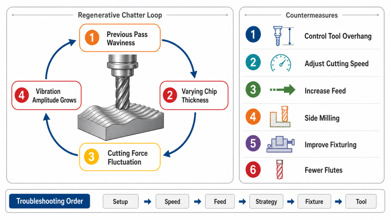
Erzwungenes Rattern wird durch externe Vibrationsquellen verursacht – Spindelrundlauf, Werkstückunwucht, Zahneingriffsfrequenzen – mit einer Frequenz, die der Quelle entspricht. Die Lösung besteht darin, die Quelle zu finden und zu beseitigen. Selbsterregtes Geschwätz (regeneratives Geschwätz) ist der häufigste Typ, durch den Schneidvorgang selbst verursacht werden: Das vom vorherigen Durchgang hinterlassene Wellenmuster interagiert mit der unterschiedlichen Spandicke beim nächsten Durchgang, Es entsteht eine Rückkopplungsschleife mit wachsender Amplitude. Über 90% Das Rattern bei der Bearbeitung von rostfreiem Stahl ist selbsterregt, Die Lösung besteht darin, die Schnittbedingungen zu ändern und die regenerative Rückkopplungsschleife zu unterbrechen.
Lösung: Verbessern Sie die Steifigkeit und unterbrechen Sie die regenerative Rückkopplungsschleife
Der Werkzeugüberhang ist der kritischste Faktor. Je länger der Überhang, Je geringer die Steifigkeit, desto leichter tritt Rattern auf. Wir kontrollieren den Überhang streng auf das 3- bis 4-fache des Werkzeugdurchmessers; Bei mehr als 5x verwenden wir vibrationsgedämpfte Werkzeughalter oder verkürzen den Überhang – Dies ist die wirksamste Maßnahme. Zu Schnittparametern, Reduzierung der Schnittgeschwindigkeit (Du bist unten 20-30%) verschiebt die Schnittkraftfrequenz aus dem Resonanzbereich; gleichzeitig Erhöhung des Vorschubs pro Zahn (fz) erhöht die Spandicke, Reduzierung der Reibung an der gehärteten Schicht und Verringerung der Ratterneigung. Natürlich, Ein übermäßiger Vorschub beeinträchtigt die Oberflächengüte, Das Gleichgewicht hängt also von den Anforderungen ab.
Zur Werkzeugwegstrategie, Wir wechseln vom Vollnutfräsen zum Seitenfräsen (radiale Breite ae = 25-50% des Werkzeugdurchmessers), Ändern der Schnittkraftrichtung und Reduzieren von Rattern. In einigen Fällen, Der Wechsel vom Steig- zum konventionellen Fräsen verbessert tatsächlich die Stabilität – Dies erfordert eine praktische Erprobung. Auch die Festigkeit der Werkstückspannung darf nicht außer Acht gelassen werden; Ein übermäßiger Werkstücküberhang oder eine schlechte Befestigung sind eine häufige Ursache für Rattern. Wir verwenden Reitstockunterstützung, zusätzliche Lünetten, und verkürzter Werkstücküberstand; für dünnwandige Teile, Spezielle Vorrichtungen oder Füllungen aus Legierungen mit niedrigem Schmelzpunkt erhöhen die Steifigkeit. Für mehrflächige Edelstahlteile, 5-Achsbearbeitung kann Fehler beim erneuten Spannen reduzieren und die Steifigkeitsplanung verbessern.
Chatter-Trigger | Überprüfen Sie die Richtung | Lösung |
Zu großer Werkzeugüberhang | Überhang / D-Verhältnis > 4 | Überhang kürzen, Hartmetallhalter, Antivibrationshalter |
Falsche Schnittgeschwindigkeit | Im Resonanzbereich | Vc reduzieren 20-30%, oder eine Feinabstimmung weg von der Resonanz vornehmen |
Zu wenig Futter | Reiben auf der verhärteten Schicht | fz erhöhen, Stellen Sie sicher, dass die Spandicke die gehärtete Schicht übersteigt |
Zu große radiale Breite | Vollnutfräsen | Wechseln Sie zum Seitenfräsen, ae = 25-50% DC |
Schlechte Werkstücksteifigkeit | Überhang / dünne Wand | Reitstock, stetige Ruhe, spezielles Gerät |
Zu viele Flöten | 6+ Flöten | Wechseln Sie zu 2-4 Flöte, Kraftschwankungen reduzieren |
Fallstudie
Internes Fertigfräsen von 304 Bei dünnwandigen Edelstahlgehäusen handelt es sich um ein typisches Ratter-Szenario. Wir haben einmal eine Charge davon bearbeitet 2 mm Wandstärke, 150 Gehäuse mit einem Durchmesser von mm, bei denen die fertiggefräste Innenfläche deutliche Rattermarken aufwies, Ra springt vom Erforderlichen 1.6 ähm zu 6.3 eins, Rundheit außerhalb der Toleranz, und hohe Maschinengeräusche. Die Untersuchung ergab einen Werkzeugüberhang 120 mm (16 mm Durchmesser, 7.5x-Verhältnis), 6-Nutfräser beim Vollnutfräsen, Vc=100 m/min, fz=0,05 mm/z – übermäßiger Überhang + zu viele Flöten + zu wenig Futter, klassisches selbsterregtes Geschwätz.
Nach der Anpassung, Werkzeugüberhang verkürzt auf 60 mm (3.75x Durchmesser), auf 4-schneidigen Hartmetall-Schaftfräser umgestellt, auf Seitenfräsen umgestellt (ae=40 % Dc), Vc reduziert auf 80 m/min, fz erhöht auf 0.12 mm/z, und ein ausziehbarer Dorn stützte das Werkstück innen für zusätzliche Steifigkeit. Chatter wurde eliminiert, Oberflächenbeschaffenheit stabilisiert bei Ra 1.6 eins, Rundheit verbesserte sich von 0.08 mm bis 0.02 mm, und Bearbeitungszeit reduziert 20%. Dieser Fall veranlasste uns, einen Standard zur Bewertung der Spannsteifigkeit für die Bearbeitung dünnwandiger Teile festzulegen.
JADE-CNC-Standardisierungsprozess
Der Überhang des Fräswerkzeugs aus rostfreiem Stahl wird innerhalb des 4-fachen Durchmessers streng kontrolliert; Für mehr als 4x ist ein Hartmetallhalter oder ein Antivibrationshalter erforderlich; Dünnwandige Teile werden vor der Bearbeitung einer Prüfung der Spannsteifigkeit unterzogen, mit Reitstock, stetige Ruhe, oder spezielle Vorrichtungen nach Bedarf; radiale Breite kontrolliert bei 25-50% des Werkzeugdurchmessers, Vollnut-Schlichtfräsen verboten; Werkzeuge verwenden 2-4 Hartmetall-Schaftfräser mit Nut. Die Erstbearbeitung überwacht den Maschinenlärm – Das erkannte Rattern löst einen sofortigen Stopp und eine Fehlerbehebung aus: Überhang -> Befestigung -> Parameter -> Werkzeugweg -> Werkzeuge. Nach Auflösung des Chatters, Parameter werden aufgezeichnet und im Teileprozessblatt standardisiert.
Verhütung: Reduzieren Sie Bearbeitungsprobleme an der Quelle
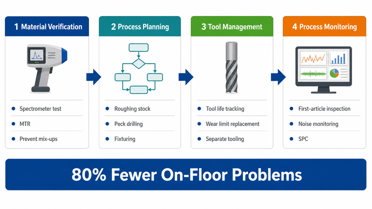
Nachdem ich alle vier Probleme abgedeckt habe, In der tatsächlichen Produktion treten diese Probleme häufig gleichzeitig auf und interagieren. Aufbauschneiden beschleunigen den Werkzeugverschleiß, Werkzeugverschleiß führt zu Rattern, und Rattern führt zum Bruch des Bohrers. Der wirklich wirksame Ansatz ist die Prävention an der Quelle, keine Behebung nach Auftreten von Problemen.
Die Überprüfung des eingehenden Materials ist die erste Verteidigungslinie. Eine falsche Materialqualität ist die Ursache vieler Bearbeitungsprobleme – 304 ausgegeben als 316, recyceltes Material mit nicht spezifikationsgerechter Zusammensetzung, Alle verursachen eine abnormale Bearbeitbarkeit. JADE-CNC kann die Zusammensetzung eingehender Materialien durch Spektrometertests überprüfen, und Materialtestberichte werden mit jeder Bestellung geliefert, Vermeidung materieller Probleme an der Quelle. Auch kritische Dimensionen und Nachbearbeitungsergebnisse können verknüpft werden CNC-Inspektion Anforderungen.
Die Prozessplanung ist die zweite Linie. Vor der Bearbeitung, Wir entwickeln eine Prozessroute basierend auf der Materialqualität und der Teilegeometrie, ausreichend Rohmaterial belassen (typischerweise 0.3-0.5 mm) um ein Nachbearbeiten der ausgehärteten Schicht zu vermeiden; Planen Sie die Bohrparameter für tiefe Löcher im Voraus; und Konstruktion von Vorrichtungen für dünnwandige Teile. Eine gute Prozessplanung reduziert die Probleme auf dem Boden beim Material erheblich, Geometrie, und Inspektionsanforderungen sind vor der Produktion klar.
Die Werkzeugverwaltung ist die dritte Zeile. Wir kümmern uns um das Standzeitmanagement, Aufzeichnung der Werkzeugstandzeit pro Material und Arbeitsgang, Austausch am Ende der Lebensdauer, anstatt auf Absplitterungen oder Brüche zu warten. Der Werkzeugbestand ist nach Material kategorisiert – Spezialwerkzeuge aus Edelstahl (Kobaltbohrer, TiAlN-Einsätze, Antivibrationshalter) werden separat verwaltet und niemals mit Aluminiumwerkzeugen vermischt.
Über JADE-CNC
JADE-CNC ist auf die Präzisionsbearbeitung von Edelstahl spezialisiert. Mit 5-Achs-Bearbeitungszentren, Dreh-Fräsmaschinen, Präzisionsschleifgeräte, und ISO 9001 Zertifizierung, Wir haben umfangreiche Produktionsdaten zu Edelstahl 304/316/316L gesammelt. Von der Werkzeugauswahl über die Parameteroptimierung bis hin zur Prozessplanung, Wir kontrollieren die Aufbaukante, Werkzeugverschleiß, kaputte Bohrer, und Rattern, um den Ertrag und die pünktliche Lieferung in der Serienproduktion zu unterstützen.
Senden Sie Ihre Zeichnungen und Materialanforderungen für eine Prozessbewertung, Werkzeugplan, und zitieren durch die JADE-CNC-Kontaktseite – typischerweise innerhalb 24 Std..
Verwandte Artikel aus Edelstahl
- CNC-Bearbeitung von Edelstahl: Der vollständige Leitfaden zur Problemlösung
- 304 vs 316 vs. Edelstahl 316L: Welches sollten Sie für die CNC-Bearbeitung wählen??
- 17-4PH-Edelstahlbearbeitung: Lösungsbehandlung, Alterung und Fertigbearbeitung
- Leitfaden zur Oberflächenveredelung von Edelstahl: Polieren, Bürsten, Sprengen, Passivierung, Elektropolieren & PVD
- Kosten für die CNC-Bearbeitung von Edelstahl & Angebotsleitfaden: 10 Kostenfaktoren und Lieferantenvergleich
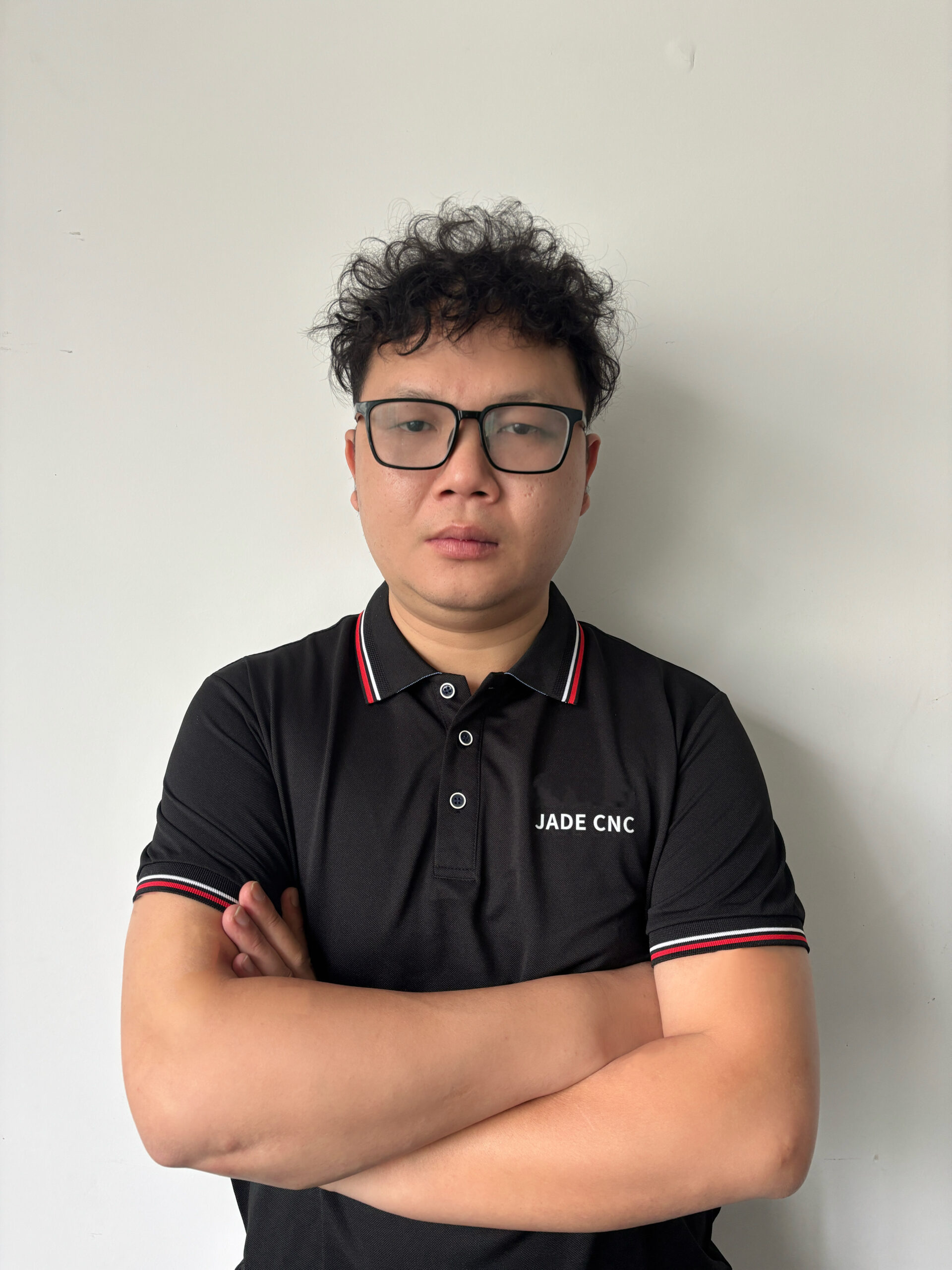
Leo Liang, Gründer Bester Partner mit R&D
JADE-CNCs Gründer LEO, der über zwei Jahrzehnte Branchenexpertise mitbringt, Leo begann seine Karriere als Lehrling und erprobte seine Fähigkeiten in der Oberflächenbehandlung und CNC-Bearbeitung.