



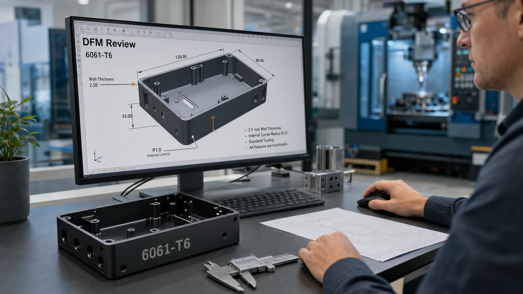
Règles de conception pour les ingénieurs préparant des pièces en aluminium 6061-T6 pour l'usinage CNC, citant, inspection, et finition.
URL suggérée: 6061-Directives DFM pour l'usinage CNC T6
Méta description: Directives DFM pratiques d'usinage CNC 6061-T6 couvrant l'épaisseur de paroi, trous, fils de discussion, rayons d'angle, tolérances, allocation d'anodisation, montage, dessins, et une liste de contrôle de sortie.
Introduction
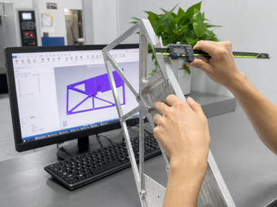
DFM est l'endroit où de nombreux projets en aluminium 6061-T6 gagnent ou perdent du temps. L'alliage usine proprement, ça se termine bien, et convient à une large gamme de supports, logements, luminaires, pièces optiques, composants robotiques, et assemblages industriels. Pourtant un dessin avec de fines parois non soutenues, petits rayons internes, tolérances strictes inutiles, ou des exigences d'anodisation peu claires peuvent encore devenir coûteuses à usiner et difficiles à inspecter.
Ce guide donne des règles de conception pratiques pour les pièces usinées CNC 6061-T6 avant que le modèle CAO ne soit publié pour devis ou production.. Il fait partie du projet JADE-CNC 6061 cluster de contenu et se connecte avec le plus large 6061-Guide complet d'usinage CNC en aluminium T6, le 6061-Guide des paramètres d'usinage CNC T6, et le 6061-Guide des propriétés de l'aluminium T6.
Utilisez ces règles comme cadre de revue de conception plutôt que comme limite universelle fixe. La fabricabilité finale dépend de la taille de la pièce, accès aux outils, rigidité de la machine, nombre de configurations, méthode d'inspection, finition de surface, et la fonction de chaque fonctionnalité.
Priorités DFM rapides pour les pièces CNC 6061-T6
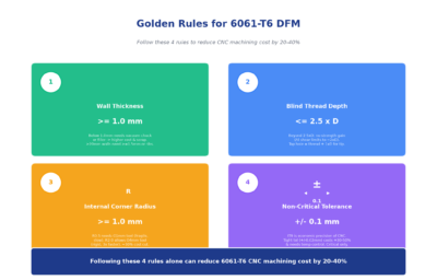
Les quatre règles qui permettent généralement d'économiser le plus de coûts
- Gardez les murs non critiques à 1.0 mm ou plus épais chaque fois que la fonction le permet.
- Utiliser des rayons d’angle internes généreux, surtout dans les poches profondes et les cavités étroites.
- Limiter l'engagement du filetage borgne à la longueur utile au lieu de spécifier une profondeur excessive.
- Appliquer des tolérances strictes uniquement aux interfaces fonctionnelles, pas à toutes les dimensions du dessin.
Ces décisions réduisent l'usinage de petits outils, risque de configuration, bavarder, retravailler, et temps d'inspection inutile. Ils rendent également le devis plus clair, car le fournisseur peut choisir des outils et des accessoires stables au lieu de construire l'ensemble du processus autour de problèmes évitables..
Conception pour l'ensemble du parcours, Pas seulement le coupeur
Une pièce pouvant être fabriquée en 6061-T6 n'est pas seulement facile à découper. Il est également facile à serrer, ébavurer, finition, inspecter, emballer, et assembler. Un modèle CAO propre peut toujours échouer dans DFM s'il ne possède pas de surface de référence fiable., si l'anodisation modifie un alésage de précision, ou si une fine paroi jaillit après la configuration finale. JADE-CNC examine ces problèmes lors du devis afin que le plan de processus corresponde à la fonction de la pièce avant le début de l'usinage..
Sélection des matériaux et des processus
Préciser clairement l'alliage et la trempe. Écrivez 6061-T6 sur le dessin plutôt qu'une légende générique en aluminium.. Pour les tôles épaisses ou les pièces où le mouvement des contraintes est un problème, 6061-Le T651 peut être un meilleur choix car il soulage le stress par les étirements. Lorsque la résistance ou le volume poussent la conception hors de la plage naturelle de l'usinage 6061-T6, comparer les alternatives dès le début au lieu de reconcevoir après le devis.
Scénario | 6061-Ajustement d'usinage CNC T6 | Alternative à considérer |
Du prototype à la production en faible volume | Ajustement solide pour une itération rapide et des pièces fonctionnelles précises. | Aucun, sauf si la géométrie est de type feuille ou extrusion. |
Pièces usinées à haute résistance | Bon ajustement quand force, résistance à la corrosion, et finir l'affaire. | 7075-T6 si une résistance plus élevée vaut le coût et le compromis d'anodisation. |
Des logements complexes à très gros volumes | Utile pour les prototypes et la production de ponts. | Moulage sous pression ADC12 lorsque le coût de l'outillage est justifié par la quantité. |
Supports ou couvercles pliés simples | Peut être sur-spécifié. | 5052 la tôle peut réduire les coûts des pièces formées à plat. |
Sections constantes longues | L'usinage à partir de billettes peut gaspiller de la matière. | 6063 extrusion plus usinage secondaire. |
Pour une comparaison axée sur les points forts, voir 6061-T6 contre aluminium 7075-T6. Pour la sélection de processus à grand volume, le guide prévu 6061-T6 contre aluminium ADC12: Usinage CNC ou moulage sous pression? est la prochaine lecture naturelle.
Épaisseur de paroi et conception à paroi mince
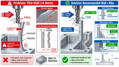
6061-Le T6 a un module élastique beaucoup plus faible que l'acier, afin que les parois fines puissent bouger pendant la coupe et ressortent après le desserrage. Cela ne veut pas dire mince 6061 les murs sont impossibles. Cela signifie la hauteur du mur, longueur non prise en charge, engagement de la fraise, porte-pièce, et les conditions d'inspection doivent être conçues ensemble.
État des fonctionnalités | Portée possible | Cible de conception préférée | Remarque DFM |
Petits murs en dessous 10 mm de hauteur | 0.5-0.8 mm | >=1,0 mm | Les sections minces peuvent nécessiter un support spécial, passes de finition légères, et une attention d'inspection plus élevée. |
Murs 10-20 mm de hauteur | 0.8-1.0 mm | >=1,2 mm | Augmentez l'épaisseur ou ajoutez des nervures lorsque le mur doit conserver sa planéité ou sa précision de positionnement.. |
Murs au-dessus 20 mm de hauteur | 1.5 mm ou plus | >=2,0 mm ou nervuré | Les murs hauts se déplacent sous l’effet de la force de coupe. Dégrossir progressivement les deux côtés et terminer une fois la tension retombée. |
Grands panneaux fins | Selon le cas | Côtes, les patrons, ou stock sacrificiel | Panneaux plus grands qu'environ 100 x 100 mm sont plus sensibles à la déformation lorsque l'épaisseur est inférieure 1.5 mm. |
Guide pour les pièces 6061-T6 usinées CNC. Confirmer les limites finales avec la taille de la pièce, géométrie, stratégie de montage, et exigences de tolérance.
Murs et nervures uniformes
Une épaisseur de paroi uniforme est plus facile à usiner et moins susceptible de se déformer. Des transitions d'épaisseur soudaines créent une rigidité inégale et peuvent provoquer des mouvements locaux lors de l'ébauche ou de la finition.. Pour des sections larges et fines, ajouter des nervures plutôt que de simplement resserrer les tolérances. Une côte pratique est souvent 60-80% de l'épaisseur de la paroi, avec un filet de racine qui évite une forte concentration de stress.
Stock sacrificiel et fonctionnalités de support
Si la géométrie finale est délicate, concevoir des onglets sacrificiels, une base temporaire, ou du stock supplémentaire qui peut être supprimé lors de la dernière configuration. Cela donne au machiniste un moyen de maintenir la pièce pendant que les surfaces critiques sont créées.. Pour le travail de prototype, cette petite quantité de matériau supplémentaire coûte souvent moins cher que la lutte contre les vibrations et les distorsions sur chaque pièce.
Trou, Chef, et conception de fils
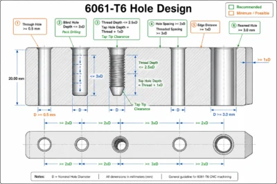
Les trous et les filetages semblent simples sur un dessin, mais ils déterminent le choix des outils, temps de cycle, risque de casse, effort d'inspection, et fiabilité de l'assemblage. Les problèmes les plus coûteux proviennent généralement de très petits trous, trous borgnes profonds, distance au bord insuffisante, et des profondeurs de filetage qui dépassent la résistance utile de l'aluminium.
Fonctionnalité | Minimum pratique | Cible préférée | Règle de conception |
Trou percé | 0.3-0.5 mm | >=0,8 mm si possible | Les petits forets se cassent facilement et nécessitent une évacuation soigneuse des copeaux. |
Filetage taraudé | M1.6 possible | M3 ou plus | Les filetages inférieurs à M3 augmentent le risque de taraudage et la difficulté d'inspection. |
Profondeur du trou borgne | Jusqu'à 5 x D avec planification des processus | <=3 x D préféré | Les trous borgnes profonds nécessitent un contrôle des copeaux, forets adaptés, et un dégagement inférieur suffisant. |
Profondeur de filetage borgne | Jusqu'à 2.5 xD | 1.5-2.0 xD | Un engagement supplémentaire ajoute rarement une résistance utile à l'aluminium mais augmente le risque de taraudage. |
Distance du bord du trou | >=1xD | >=1,5xD | Une plus grande distance au bord réduit les cassures, distorsion, et des patrons faibles. |
Espacement trou à trou | >=2xD | >=3 x D pour les fonctionnalités filetées | Les fonctionnalités filetées nécessitent plus de matériau autour du petit diamètre. |
Trous borgnes
Un trou borgne a besoin d'espace en dessous de la profondeur fonctionnelle pour la pointe de forage, puces, et outil de création de filetage. Lorsque le modèle affiche uniquement la profondeur de filetage finie, le processus peut ne pas avoir de place pour créer un thread complet en toute sécurité. Ajoutez un dégagement inférieur ou autorisez un trou traversant lorsque la conception le permet.
Engagement dans le fil de discussion
Plus la profondeur du filetage n'est pas toujours plus forte. En aluminium, l'engagement utile des threads atteint souvent une limite pratique autour 1.5-2.0 fois le diamètre nominal pour de nombreux assemblages. Au-delà de ça, risque de casse de robinetterie, temps de cycle, et le contrôle des puces devient plus important que l'engagement supplémentaire. Pour les articulations critiques, calculer l'engagement requis à partir de la charge, matériau de fixation, forme de fil, et facteur de sécurité.
Trous taraudés après anodisation
Si la pièce sera anodisée, décider si les fils de discussion sont masqués, coupé après anodisation, ou poursuivi après anodisation. Cela devrait être écrit sur le dessin. Le laisser implicite peut provoquer un assemblage serré, couple incohérent, ou des dommages au revêtement lors de l'installation.
Rayons et congés des coins internes
Le rayon d'angle interne est l'un des facteurs de coûts les plus évidents dans le fraisage CNC. Un petit rayon intérieur oblige à utiliser une petite fraise. Les petits outils sont moins rigides, retirer la matière plus lentement, et sont plus sensibles au faux-rond et à la casse. Si le coin ne contrôle pas la fonction, agrandissez-le.
Zone | Minimum | Préféré | Pourquoi c'est important |
Poches internes générales | R0,5mm | R1,0 mm ou plus | Un rayon plus grand permet une fraise plus solide et une avance plus rapide. |
Poches profondes | R1,0 mm | R2,0 mm ou plus | Portée de l'outil, déviation, et l'évacuation des copeaux deviennent les facteurs limitants. |
Racines de bossage et de côtes | R0,3-R0,5 mm | >=0,5 x épaisseur de paroi | Les congés de racine réduisent la concentration des contraintes et améliorent l'accès aux outils. |
Bords externes | C0,2-C0,5 mm ou R0,2-R0,5 mm | Rupture de bord définie | Un bord contrôlé réduit les bavures et contribue à la qualité de finition. |
Faire correspondre le rayon à l'accès à l'outil
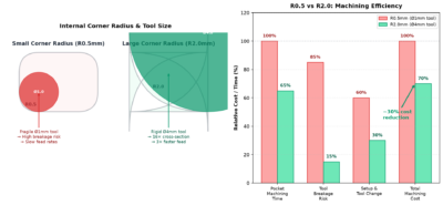
Une poche avec des coins de R0,5 mm peut nécessiter un 1 mm cutter pour le nettoyage. La même poche avec des coins R2,0 mm peut souvent utiliser un outil beaucoup plus puissant. L'effet s'accentue à mesure que la profondeur de la poche augmente, car la portée et la déviation de l'outil deviennent dominantes.. Si un coin interne pointu est requis pour l'assemblage, envisager un créneau de secours, coin en os de chien, ou une opération secondaire locale au lieu de rendre toute la poche difficile.
Ruptures de bord externes
Ne laissez pas les bords entièrement ouverts lorsque la pièce est manipulée., assemblée, cosmétique, ou exigences de finition. Un petit chanfrein tel que C0,2-C0,5 mm ou un petit rayon peut contrôler les bavures et rendre l'anodisation plus cohérente. Pour surfaces d'étanchéité ou interfaces coulissantes, définir soigneusement la rupture de bord afin que la finition prenne en charge la fonction.
Stratégie de tolérance et de référence
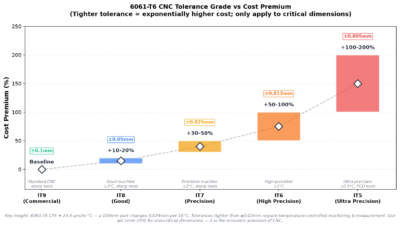
Les tolérances doivent décrire la fonction, pas de prudence. 6061-T6 peut être usiné avec précision, mais des tolérances serrées multiplient les coûts lorsqu'elles nécessitent un contrôle de configuration supplémentaire, inspection, stabilisation de la température, changements d'outils, ou des passes de finition plus lentes. Un dessin qui utilise une tolérance générale réaliste et ne resserre que les caractéristiques critiques est généralement plus rapide à proposer et plus facile à fabriquer..
Type d'exigence | Choix de conception typique | Effet des coûts | Orientations DFM |
Dimensions non critiques | +/-0.10 mm ou tolérance générale de dessin | Référence | Évitez les tolérances strictes sur les produits cosmétiques, autorisation, ou dimensions non correspondantes. |
Alésages ou arbres correspondants | +/-0.02 à +/-0.05 mm en cas de besoin | Modéré à élevé | Utiliser la cotation directe à partir de références stables et définir la méthode d'inspection. |
Platitude / parallélisme | DG&T là où la fonction l'exige | Modéré | Contrôler la distorsion de serrage et spécifier si la pièce est mesurée à l'état libre ou retenue. |
Position réelle / profil | GD basé sur les données&T | Modéré à élevé | Utiliser des fonctions de référence claires au lieu de cotes chaînées. |
Fonctionnalités ultra-serrées | Ci-dessous +/-0.02 mm | Haut | Confirmer la température, capacité du processus, et incertitude d'inspection avant la libération. |
Utiliser des références au lieu de cotes chaînées
Les dimensions chaînées accumulent les variations d'une fonctionnalité à l'autre. Pour les pièces qui doivent s’assembler proprement, définir des caractéristiques de référence stables et dimensionner les trous critiques, alésages, machines à sous, et fait face à ces données. Cette approche facilite également l'inspection car la configuration de mesure peut simuler les mêmes références fonctionnelles utilisées dans l'assemblage..
Pour les systèmes de tolérance et les spécifications géométriques des produits, les références utiles incluent OIN 286-1 pour les tolérances dimensionnelles linéaires et OIN 1101 pour tolérancement géométrique. Ces normes ne remplacent pas le jugement technique, mais ils aident à garder les dessins interprétables par les fournisseurs et les équipes d'inspection.
Conditions de température et de mesure
L'aluminium se dilate plus que l'acier. Lorsqu'une pièce 6061-T6 présente des caractéristiques limitées à quelques centièmes de millimètre, la température peut devenir visible dans les résultats de l’inspection. Si une dimension est très serrée, spécifier les conditions de mesure et éviter de mélanger les contrôles en atelier à différentes températures avec l'inspection finale dans des conditions de référence contrôlées.
Traitement de surface et allocation d'anodisation
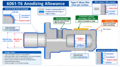
Le traitement de surface doit être conçu avant la publication du dessin. L'anodisation peut améliorer la résistance à la corrosion, performance à l'usure, et l'apparence, mais cela change aussi les dimensions et peut affecter les filetages, alésages, faces de contact électrique, et attentes cosmétiques. La conception doit indiquer quelles surfaces sont finies, quelles surfaces sont masquées, et si les dimensions sont interprétées avant ou après la finition.
Article de conception | Règle DFM | Raison |
Épaisseur d'anodisation | Type d'état, couleur, épaisseur, et si les dimensions s'appliquent avant ou après l'anodisation. | Le film anodique change de taille et peut affecter les ajustements. |
Trous filetés | Appelez le masquage ou le filage après l'anodisation. | L'accumulation de revêtement peut réduire l'ajustement du filetage et augmenter le couple d'assemblage. |
Zones de contact conductrices | Marquer comme non anodisé ou masqué. | L'aluminium anodisé est électriquement isolant. |
Arêtes vives | Casser les bords avant l'anodisation. | Les coins pointus peuvent recevoir un film mince, montrer brûlant, ou exposer la variation de couleur. |
Visages cosmétiques | Identifier les surfaces visibles et la direction du grain, le cas échéant. | Marques d'outils, dynamitage, et la couleur d'anodisation doivent être planifiées ensemble. |
Pour une planification spécifique à la finition, lier cet article au 6061-Guide d'anodisation en aluminium T6. Les légendes sur la texture de la surface doivent également être écrites de manière cohérente; OIN 21920-1 pour la spécification du profil d'état de surface est une référence externe utile lorsque les exigences de dessin nécessitent une interprétation formelle.
Fixation, Nombre de configurations, et accès aux outils
Chaque configuration supplémentaire ajoute du temps de traitement et une nouvelle opportunité de changement de référence. Un bon DFM donne au machiniste des moyens stables de conserver le stock, machine les principales caractéristiques, et inspecter la pièce à partir des références prévues. Si la pièce n'a pas de surface de serrage plate, pensez à ajouter des languettes temporaires ou du matériel sacrificiel. Si la pièce doit être accessible depuis plusieurs directions, décider si la géométrie nécessite réellement un usinage sur 5 axes ou si une petite modification de conception peut réduire le nombre de configurations.
Concevoir en pensant à la première configuration
La première configuration doit créer des données fiables pour des travaux ultérieurs dans la mesure du possible. Grandes surfaces planes, localisation des alésages, ou des patrons robustes peuvent aider. Évitez de forcer le fournisseur à serrer uniquement sur des murs finis minces, visages cosmétiques, ou bords flexibles. Où le design est sensible, JADE-CNC équipe d'usinage CNC sur mesure peut revoir les concepts de luminaires avant de citer les quantités de production.
Accès aux outils et contre-dépouilles
Contre-dépouilles, poches cachées, fentes étroites, et les cavités profondes doivent être intentionnelles. Si un outil vertical ou horizontal standard ne peut pas atteindre la fonction, la pièce peut nécessiter des fraises spéciales, configurations en angle, GED, ou usinage 5 axes. Ajouter un relief local ou modifier l'orientation de l'entité lorsque la fonction le permet.
Liste de contrôle de publication des dessins
Un package de version propre réduit les allers-retours avant le devis et empêche les hypothèses de fabrication de devenir des décisions de conception cachées.. Le dessin n'a pas besoin de sur-spécifier chaque surface, mais il doit identifier les fonctionnalités importantes pour fonctionner, inspection, finition, et assemblage.
Libérer l'élément | Que faut-il inclure | Problème courant évité |
3Modèle D | Fichier STEP avec la géométrie finale. | Ambiguïté entre modèle et dessin. |
2Dessin D | Dimensions critiques, la date, tolérances, finition, quantité, et révision. | Hypothèses de devis et exigences fonctionnelles manquées. |
Légende du matériau | 6061-T6 ou 6061-T651 lorsqu'un soulagement du stress est requis. | Mauvaise humeur ou mouvement excessif dans les pièces épaisses. |
Terminer l'accroche | Type/couleur/épaisseur d'anodisation, masquage, surfaces cosmétiques, et dimensions post-finition. | Problèmes d'assemblage une fois terminé. |
Plan de contrôle | Caractéristiques critiques pour la qualité et conditions de mesure. | Arguments sur les critères d'acceptation après la fabrication des pièces. |
Liste de contrôle DFM préalable au devis
Catégorie | Vérifier avant la sortie |
Matériel | L'alliage et l'état sont spécifiés comme 6061-T6 ou 6061-T651, le cas échéant.. |
Action | La pièce s'adapte à la plaque commune, bar, ou du matériel d'extrusion avec une surépaisseur d'usinage raisonnable. |
Épaisseur de paroi | Les murs sont >=1,0 mm si possible, et les zones hautes ou larges et minces comprennent des nervures ou une stratégie de support. |
Trous | Petits trous, trous profonds, et les trous borgnes ont suffisamment d'accès aux outils et de dégagement des copeaux. |
Sujets | La profondeur du filetage borgne est normalement 1.5-2.0 xD, avec profondeur pilote et dégagement inférieur définis. |
Coins | Les rayons internes sont suffisamment grands pour une taille de coupe pratique; les poches profondes évitent les petits rayons de coin. |
Bords | Les arêtes externes incluent un chanfrein ou un rayon contrôlé au lieu d'arêtes vives non spécifiées. |
Tolérances | Des tolérances strictes apparaissent uniquement sur les caractéristiques fonctionnelles, pas dans toutes les dimensions. |
La date | Les données sont stables, usinable, et partagé par l'usinage et l'inspection. |
Finition superficielle | Anodisation, masquage, visages cosmétiques, et les dimensions de post-finition sont définies. |
Fixation | La pièce présente des zones de serrage plates, onglets, stock sacrificiel, ou une autre approche claire de maintien du travail. |
Documentation | ÉTAPE, dessin, quantité, matériel, finition, et la révision sont fournies ensemble. |
Prise en charge de la révision JADE-CNC DFM
JADE-CNC examine la fabricabilité avant de proposer un devis pour les pièces CNC de prototype et de production. L'examen peut signaler le risque de paroi mince, problèmes d'accès aux outils, tolérances peu claires, mettre fin aux conflits, soucis de fil, et alternatives de processus. Ceci est particulièrement utile lorsqu'une pièce doit équilibrer le coût d'usinage, anodisation cosmétique, ajustement de l'assemblage, et délai de livraison.
Pour demander une révision, envoyer le modèle 3D, 2Dessin D, exigences en matière de matériaux et de finition, quantité, délai de livraison cible, et toutes les fonctionnalités essentielles à la qualité via Page contact de JADE-CNC. Pour les exigences d’inspection critiques, JADE-CNC peut également aligner le plan d'usinage avec son capacité d'inspection de la qualité.
Foire aux questions
Quelle est l'épaisseur de paroi minimale recommandée pour les pièces CNC 6061-T6?
Pour de nombreuses pièces, 1.0 mm est une cible inférieure pratique pour les murs courts. Les parois minces plus hautes ou plus larges doivent être plus épaisses, côtelé, ou soutenu par un stock sacrificiel. Caractéristiques ci-dessous 1.0 mm peut être possible, mais ils devraient être revus pour la hauteur, longueur, tolérance, accès aux outils, et méthode de serrage.
Quelle doit être la profondeur des trous taraudés borgnes dans le 6061-T6?
Un objectif de conception courant est 1.5-2.0 fois le diamètre nominal du filetage pour un engagement utile, avec suffisamment de profondeur pilote supplémentaire pour la pointe du taraud et les copeaux. Des fils aveugles plus profonds peuvent être réalisés, mais ils ajoutent souvent un risque de taraudage sans grand bénéfice fonctionnel, sauf si le calcul conjoint l'exige.
Quand dois-je resserrer les tolérances ci-dessous +/-0.05 mm?
Serrer en dessous +/-0.05 mm uniquement lorsque les commandes de fonctionnalités s'adaptent, alignement, scellage, mouvement, ou une autre fonction mesurable. Alors définissez des dates, méthode d'inspection, et conditions de mesure. Si la fonctionnalité est cosmétique ou nécessite uniquement une autorisation, une tolérance plus lâche réduit généralement les coûts sans réduire les performances.
Comment l'anodisation doit-elle être représentée sur un dessin 6061-T6?
Indiquer le type d'anodisation, couleur, plage d'épaisseur, zones masquées, visages cosmétiques, et si les dimensions s'appliquent avant ou après l'anodisation. Pour alésages de précision et trous filetés, ajouter une note claire pour le masquage, usinage post-finition, ou chasse-fil.
L'usinage CNC est-il toujours meilleur que le moulage sous pression pour les conceptions 6061-T6?
Non. L'usinage CNC est souvent meilleur pour les prototypes, production en faible volume, tolérances serrées, et des conceptions qui peuvent encore changer. Le moulage sous pression peut devenir plus économique pour les boîtiers complexes à grand volume, mais l'alliage, investissement en outillage, conception de mur, brouillon, et les attentes en matière de finition sont différentes.
Articles connexes sur le 6061-T6
- 6061-Guide complet d'usinage CNC en aluminium T6
- 6061-T6 contre aluminium 7075-T6: Force, Coût & Usinabilité
- 6061-Anodisation de l'aluminium T6: Espèces, Couleurs, Épaisseur & Règles de conception
- 6061-Paramètres d'usinage CNC T6: Vitesses, Flux, Outillage & Contrôle des processus
- 6061-T6 contre ADC12 Aluminium: Usinage CNC ou moulage sous pression?
- 6061-Directives DFM pour l'usinage CNC T6: Règles de conception & Liste de contrôle
- 6061-Propriétés de l'aluminium T6: Mécanique, Thermique & Données chimiques

Léo Liang, Fondateur Meilleur partenaire avec R&D
LEO, fondateur de JADE-CNC, qui apporte plus de deux décennies d'expertise dans l'industrie, Leo a commencé sa carrière en tant qu'apprenti et met en pratique ses compétences en traitement de surface et en usinage CNC..