



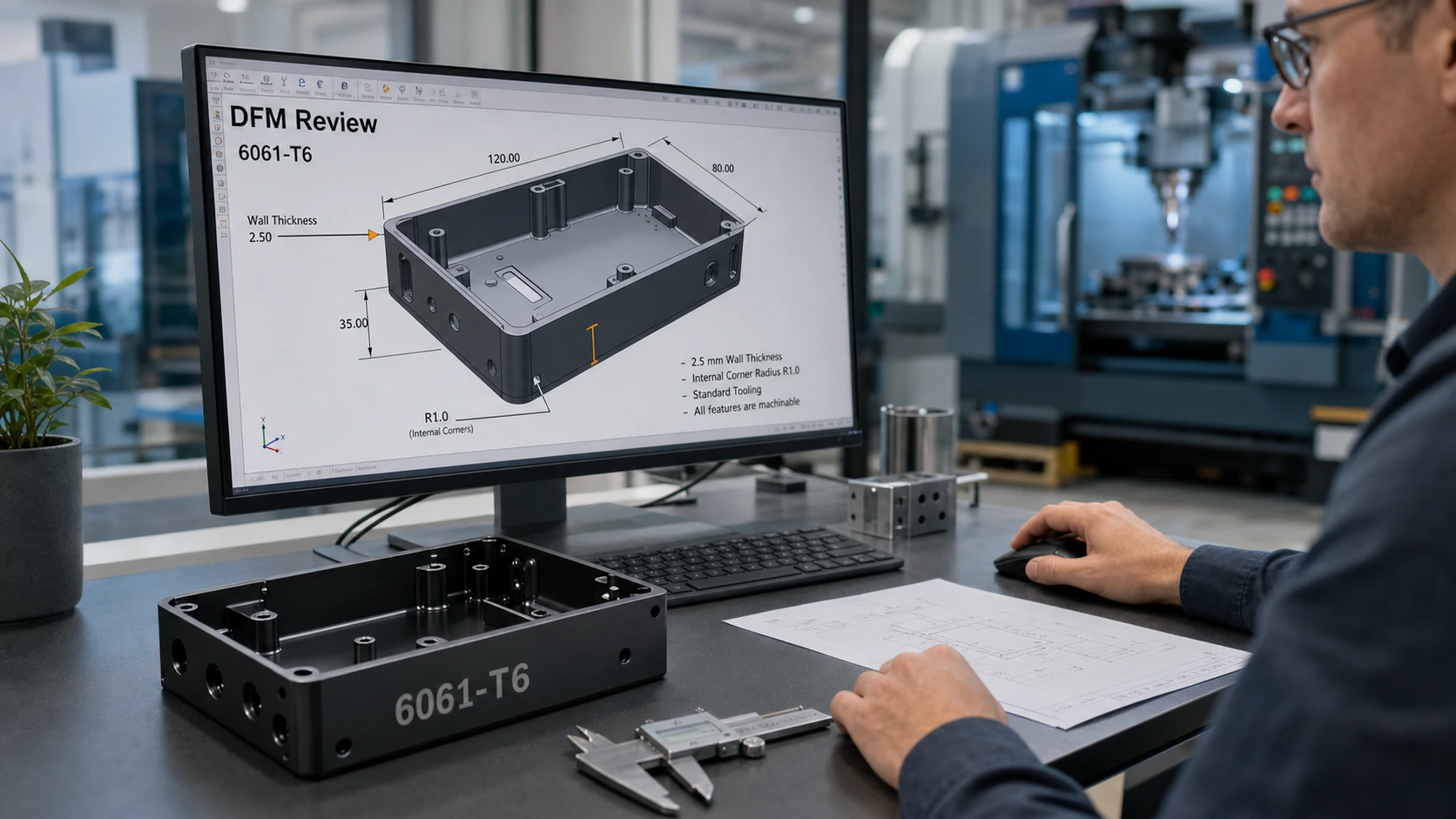
Design rules for engineers preparing 6061-T6 aluminum parts for CNC machining, quoting, inspection, and finishing.
Suggested URL: 6061-T6 CNC machining DFM guidelines
Meta description: Practical 6061-T6 CNC machining DFM guidelines covering wall thickness, holes, threads, corner radii, tolerances, anodizing allowance, fixturing, drawings, and a release checklist.
Introduction
DFM is where many 6061-T6 aluminum projects win or lose time. The alloy machines cleanly, finishes well, and suits a wide range of brackets, housings, fixtures, optical parts, robotics components, and industrial assemblies. Yet a drawing with thin unsupported walls, tiny internal radii, unnecessary tight tolerances, or unclear anodizing requirements can still become expensive to machine and difficult to inspect.
This guide gives practical design rules for 6061-T6 CNC machined parts before the CAD model is released for quotation or production. It is part of JADE-CNC’s 6061 content cluster and connects with the broader 6061-T6 aluminum CNC machining complete guide, the 6061-T6 CNC machining parameters guide, and the 6061-T6 aluminum properties guide.
Use these rules as a design review framework rather than a fixed universal limit. Final manufacturability depends on part size, tool access, machine rigidity, setup count, inspection method, surface finishing, and the function of each feature.
Quick DFM Priorities for 6061-T6 CNC Parts
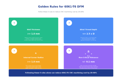
The Four Rules That Usually Save the Most Cost
- Keep non-critical walls at 1.0 mm or thicker whenever the function allows it.
- Use generous internal corner radii, especially in deep pockets and narrow cavities.
- Limit blind thread engagement to the useful length instead of specifying excessive depth.
- Apply tight tolerances only to functional interfaces, not to every drawing dimension.
These decisions reduce small-tool machining, setup risk, chatter, rework, and unnecessary inspection time. They also make the quote clearer because the supplier can choose stable tools and fixtures instead of building the entire process around avoidable problem features.
Design for the Whole Route, Not Only the Cutter
A manufacturable 6061-T6 part is not only easy to cut. It is also easy to clamp, deburr, finish, inspect, package, and assemble. A clean CAD model can still fail DFM if it has no reliable datum surface, if anodizing changes a precision bore, or if a thin wall springs after the final setup. JADE-CNC reviews these issues during quotation so the process plan matches the part’s function before machining begins.
Material and Process Selection
Specify the alloy and temper clearly. Write 6061-T6 on the drawing rather than a generic aluminum callout. For thick plate or parts where stress movement is a concern, 6061-T651 may be a better choice because it is stress relieved by stretching. When strength or volume pushes the design outside the natural range of 6061-T6 machining, compare the alternatives early instead of redesigning after quotation.
Scenario | 6061-T6 CNC machining fit | Alternative to consider |
Prototype to low-volume production | Strong fit for fast iteration and accurate functional parts. | None unless geometry is sheet-like or extrusion-like. |
High-strength machined parts | Good fit when strength, corrosion resistance, and finish matter. | 7075-T6 if higher strength is worth the cost and anodizing trade-off. |
Very high-volume complex housings | Useful for prototypes and bridge production. | ADC12 die casting when tooling cost is justified by quantity. |
Simple bent brackets or covers | May be over-specified. | 5052 sheet metal can reduce cost for flat formed parts. |
Long constant cross-sections | Machining from billet can waste material. | 6063 extrusion plus secondary machining. |
For a strength-focused comparison, see 6061-T6 vs 7075-T6 aluminum. For high-volume process selection, the planned guide 6061-T6 vs ADC12 aluminum: CNC machining or die casting? is the natural next read.
Wall Thickness and Thin-Wall Design
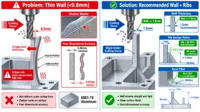
6061-T6 has much lower elastic modulus than steel, so thin walls can move during cutting and spring after unclamping. This does not mean thin 6061 walls are impossible. It means wall height, unsupported length, cutter engagement, workholding, and inspection condition must be designed together.
Feature condition | Possible range | Preferred design target | DFM note |
Small walls below 10 mm tall | 0.5-0.8 mm | >=1.0 mm | Thin sections may need special support, light finishing passes, and higher inspection attention. |
Walls 10-20 mm tall | 0.8-1.0 mm | >=1.2 mm | Increase thickness or add ribs when the wall must hold flatness or positional accuracy. |
Walls above 20 mm tall | 1.5 mm or more | >=2.0 mm or ribbed | Tall walls move under cutting force. Rough both sides gradually and finish after stress has settled. |
Large thin panels | Case dependent | Ribs, bosses, or sacrificial stock | Panels larger than about 100 x 100 mm are more sensitive to distortion when thickness is below 1.5 mm. |
Guidance for CNC-machined 6061-T6 parts. Confirm final limits with part size, geometry, fixture strategy, and tolerance requirements.
Uniform Walls and Ribs
Uniform wall thickness is easier to machine and less likely to distort. Sudden thickness transitions create uneven stiffness and can cause local movement during roughing or finishing. For broad thin sections, add ribs rather than simply tightening tolerances. A practical rib is often 60-80% of the wall thickness, with a root fillet that avoids a sharp stress concentration.
Sacrificial Stock and Support Features
If the final geometry is delicate, design sacrificial tabs, a temporary base, or extra stock that can be removed in the last setup. This gives the machinist a way to hold the part while the critical surfaces are being created. For prototype work, this small amount of extra material often costs less than fighting vibration and distortion on every part.
Hole, Boss, and Thread Design
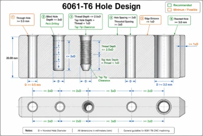
Holes and threads look simple on a drawing, but they drive tool choice, cycle time, breakage risk, inspection effort, and assembly reliability. The most expensive problems usually come from very small holes, deep blind holes, insufficient edge distance, and thread depths that exceed the useful strength of the aluminum.
Feature | Practical minimum | Preferred target | Design rule |
Drilled hole | 0.3-0.5 mm | >=0.8 mm where possible | Small drills break easily and need careful chip evacuation. |
Tapped thread | M1.6 possible | M3 or larger | Threads below M3 increase tap risk and inspection difficulty. |
Blind hole depth | Up to 5 x D with process planning | <=3 x D preferred | Deep blind holes require chip control, suitable drills, and enough bottom clearance. |
Blind thread depth | Up to 2.5 x D | 1.5-2.0 x D | Extra engagement rarely adds useful strength in aluminum but increases tapping risk. |
Hole edge distance | >=1 x D | >=1.5 x D | More edge distance reduces breakout, distortion, and weak bosses. |
Hole-to-hole spacing | >=2 x D | >=3 x D for threaded features | Threaded features need more material around the minor diameter. |
Blind Holes
A blind hole needs space below the functional depth for the drill point, chips, and thread-making tool. When the model only shows the finished thread depth, the process may have no room to create a complete thread safely. Add bottom clearance or allow a through hole when the design permits it.
Thread Engagement
More thread depth is not always stronger. In aluminum, useful thread engagement often reaches a practical limit around 1.5-2.0 times the nominal diameter for many assemblies. Beyond that, tap breakage risk, cycle time, and chip control become more important than the extra engagement. For critical joints, calculate the required engagement from the load, fastener material, thread form, and safety factor.
Tapped Holes After Anodizing
If the part will be anodized, decide whether threads are masked, cut after anodizing, or chased after anodizing. This should be written on the drawing. Leaving it implied can cause tight assembly, inconsistent torque, or coating damage during installation.
Internal Corner Radii and Fillets
Internal corner radius is one of the clearest cost drivers in CNC milling. A small inside radius forces a small end mill. Small tools are less rigid, remove material more slowly, and are more sensitive to runout and breakage. If the corner does not control function, make it larger.
Area | Minimum | Preferred | Why it matters |
General internal pockets | R0.5 mm | R1.0 mm or larger | A larger radius allows a stronger cutter and faster feed. |
Deep pockets | R1.0 mm | R2.0 mm or larger | Tool reach, deflection, and chip evacuation become the limiting factors. |
Boss and rib roots | R0.3-R0.5 mm | >=0.5 x wall thickness | Root fillets reduce stress concentration and improve tool access. |
External edges | C0.2-C0.5 mm or R0.2-R0.5 mm | Defined edge break | A controlled edge reduces burrs and helps finishing quality. |
Match Radius to Tool Access
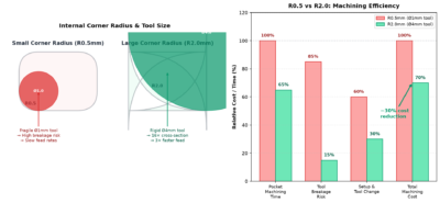
A pocket with R0.5 mm corners may require a 1 mm cutter for cleanup. The same pocket with R2.0 mm corners can often use a much stronger tool. The effect becomes larger as pocket depth increases because tool reach and deflection become dominant. If a sharp internal corner is required for assembly, consider a relief slot, dog-bone corner, or local secondary operation instead of making the whole pocket difficult.
External Edge Breaks
Do not leave edge condition entirely open when the part has handling, assembly, cosmetic, or finishing requirements. A small chamfer such as C0.2-C0.5 mm or a small radius can control burrs and make anodizing more consistent. For sealing faces or sliding interfaces, define the edge break carefully so the finish supports the function.
Tolerance and Datum Strategy
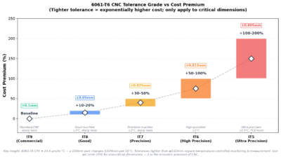
Tolerances should describe function, not caution. 6061-T6 can be machined accurately, but tight tolerances multiply cost when they require extra setup control, inspection, temperature stabilization, tool changes, or slower finishing passes. A drawing that uses a realistic general tolerance and tightens only the critical features is usually faster to quote and easier to manufacture.
Requirement type | Typical design choice | Cost effect | DFM guidance |
Non-critical dimensions | +/-0.10 mm or general drawing tolerance | Baseline | Avoid tight tolerances on cosmetic, clearance, or non-mating dimensions. |
Mating bores or shafts | +/-0.02 to +/-0.05 mm when needed | Moderate to high | Use direct dimensioning from stable datums and define inspection method. |
Flatness / parallelism | GD&T where function requires it | Moderate | Control clamping distortion and specify whether the part is measured free state or restrained. |
True position / profile | Datum-based GD&T | Moderate to high | Use clear datum features instead of chained dimensions. |
Ultra-tight features | Below +/-0.02 mm | High | Confirm temperature, process capability, and inspection uncertainty before release. |
Use Datums Instead of Chained Dimensions
Chained dimensions accumulate variation from feature to feature. For parts that must assemble cleanly, define stable datum features and dimension critical holes, bores, slots, and faces back to those datums. This approach also helps inspection because the measurement setup can simulate the same functional references used in assembly.
For tolerance systems and geometric product specifications, useful references include ISO 286-1 for linear size tolerances and ISO 1101 for geometrical tolerancing. These standards do not replace engineering judgment, but they help keep drawings interpretable across suppliers and inspection teams.
Temperature and Measurement Condition
Aluminum expands more than steel. When a 6061-T6 part has features held to a few hundredths of a millimeter, temperature can become visible in inspection results. If a dimension is very tight, specify the measurement condition and avoid mixing shop-floor checks at different temperatures with final inspection at a controlled reference condition.
Surface Treatment and Anodizing Allowance
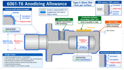
Surface treatment should be designed before the drawing is released. Anodizing can improve corrosion resistance, wear performance, and appearance, but it also changes dimensions and can affect threads, bores, electrical contact faces, and cosmetic expectations. The design should state what surfaces are finished, what surfaces are masked, and whether dimensions are interpreted before or after finishing.
Design item | DFM rule | Reason |
Anodizing thickness | State type, color, thickness, and whether dimensions apply before or after anodizing. | Anodic film changes size and can affect fits. |
Threaded holes | Call out masking or thread chasing after anodizing. | Coating buildup can reduce thread fit and increase assembly torque. |
Conductive contact areas | Mark as no anodize or masked. | Anodized aluminum is electrically insulating. |
Sharp edges | Break edges before anodizing. | Sharp corners may receive thin film, show burning, or expose color variation. |
Cosmetic faces | Identify visible surfaces and grain direction where relevant. | Tool marks, blasting, and anodizing color must be planned together. |
For finish-specific planning, link this article to the 6061-T6 aluminum anodizing guide. Surface texture callouts should also be written consistently; ISO 21920-1 for surface texture profile specification is a useful external reference when drawing requirements need formal interpretation.
Fixturing, Setup Count, and Tool Access
Every extra setup adds handling time and a new opportunity for datum shift. Good DFM gives the machinist stable ways to hold the stock, machine the key features, and inspect the part from the intended datums. If the part has no flat clamping surface, consider adding temporary tabs or sacrificial material. If the part needs access from many directions, decide whether the geometry truly requires 5-axis machining or whether a small design change can reduce setup count.
Design With the First Setup in Mind
The first setup should create reliable datums for later work whenever possible. Large flat surfaces, locating bores, or robust bosses can help. Avoid forcing the supplier to clamp only on thin finished walls, cosmetic faces, or flexible edges. Where the design is sensitive, JADE-CNC’s custom CNC machining team can review fixture concepts before quoting production quantities.
Tool Access and Undercuts
Undercuts, hidden pockets, narrow slots, and deep cavities should be intentional. If a standard vertical or horizontal tool cannot reach the feature, the part may need special cutters, angled setups, EDM, or 5-axis machining. Add a local relief or change the feature orientation when the function allows it.
Drawing Release Checklist
A clean release package reduces back-and-forth before quotation and prevents manufacturing assumptions from becoming hidden design decisions. The drawing does not need to over-specify every surface, but it should identify the features that matter to function, inspection, finishing, and assembly.
Release item | What to include | Common issue avoided |
3D model | STEP file with final geometry. | Ambiguity between model and drawing. |
2D drawing | Critical dimensions, datums, tolerances, finish, quantity, and revision. | Quote assumptions and missed functional requirements. |
Material callout | 6061-T6 or 6061-T651 where stress relief is required. | Wrong temper or excessive movement in thick parts. |
Finish callout | Anodize type/color/thickness, masking, cosmetic surfaces, and post-finish dimensions. | Assembly problems after finishing. |
Inspection plan | Critical-to-quality features and measurement condition. | Arguments over acceptance criteria after parts are made. |
Pre-Quote DFM Checklist
Category | Check before release |
Material | Alloy and temper are specified as 6061-T6 or 6061-T651 where appropriate. |
Stock | The part fits common plate, bar, or extrusion stock with reasonable machining allowance. |
Wall thickness | Walls are >=1.0 mm where possible, and tall or broad thin areas include ribs or support strategy. |
Holes | Small holes, deep holes, and blind holes have enough tool access and chip clearance. |
Threads | Blind thread depth is normally 1.5-2.0 x D, with pilot depth and bottom clearance defined. |
Corners | Internal radii are large enough for practical cutter size; deep pockets avoid tiny corner radii. |
Edges | External edges include a controlled chamfer or radius instead of unspecified sharp edges. |
Tolerances | Tight tolerances appear only on functional features, not on every dimension. |
Datums | Datums are stable, machinable, and shared by machining and inspection. |
Surface finish | Anodizing, masking, cosmetic faces, and post-finish dimensions are defined. |
Fixturing | The part has flat clamping areas, tabs, sacrificial stock, or another clear workholding approach. |
Documentation | STEP, drawing, quantity, material, finish, and revision are supplied together. |
JADE-CNC DFM Review Support
JADE-CNC reviews manufacturability before quotation for prototype and production CNC parts. The review can flag thin-wall risk, tool access issues, unclear tolerances, finishing conflicts, thread concerns, and process alternatives. This is especially useful when a part must balance machining cost, cosmetic anodizing, assembly fit, and delivery time.
To request a review, send the 3D model, 2D drawing, material and finish requirements, quantity, target lead time, and any critical-to-quality features through JADE-CNC’s contact page. For critical inspection requirements, JADE-CNC can also align the machining plan with its quality inspection capability.
Frequently Asked Questions
What is the recommended minimum wall thickness for 6061-T6 CNC parts?
For many parts, 1.0 mm is a practical lower target for short walls. Taller or broader thin walls should be thicker, ribbed, or supported by sacrificial stock. Features below 1.0 mm may be possible, but they should be reviewed for height, length, tolerance, tool access, and clamping method.
How deep should blind tapped holes be in 6061-T6?
A common design target is 1.5-2.0 times the nominal thread diameter for useful engagement, with enough extra pilot depth for the tap tip and chips. Deeper blind threads can be made, but they often add tapping risk without much functional benefit unless the joint calculation requires it.
When should I tighten tolerances below +/-0.05 mm?
Tighten below +/-0.05 mm only when the feature controls fit, alignment, sealing, motion, or another measurable function. Also define datums, inspection method, and measurement condition. If the feature is cosmetic or only needs clearance, a looser tolerance usually reduces cost without reducing performance.
How should anodizing be shown on a 6061-T6 drawing?
State the anodizing type, color, thickness range, masked areas, cosmetic faces, and whether dimensions apply before or after anodizing. For precision bores and threaded holes, add a clear note for masking, post-finish machining, or thread chasing.
Is CNC machining always better than die casting for 6061-T6 designs?
No. CNC machining is often better for prototypes, low-volume production, tight tolerances, and designs that may still change. Die casting can become more economical for high-volume complex housings, but the alloy, tooling investment, wall design, draft, and finishing expectations are different.
Related 6061-T6 Articles
- 6061-T6 Aluminum CNC Machining Complete Guide
- 6061-T6 vs 7075-T6 Aluminum: Strength, Cost & Machinability
- 6061-T6 Aluminum Anodizing: Types, Colors, Thickness & Design Rules
- 6061-T6 CNC Machining Parameters: Speeds, Feeds, Tooling & Process Control
- 6061-T6 vs ADC12 Aluminum: CNC Machining or Die Casting?
- 6061-T6 CNC Machining DFM Guidelines: Design Rules & Checklist
- 6061-T6 Aluminum Properties: Mechanical, Thermal & Chemical Data

Leo Liang, Founder Best Partner with R&D
JADE-CNC’s Founder LEO, who brings over two decades of industry expertise, Leo started his career as an apprentice and practice his skills in surface treatment and CNC machining.