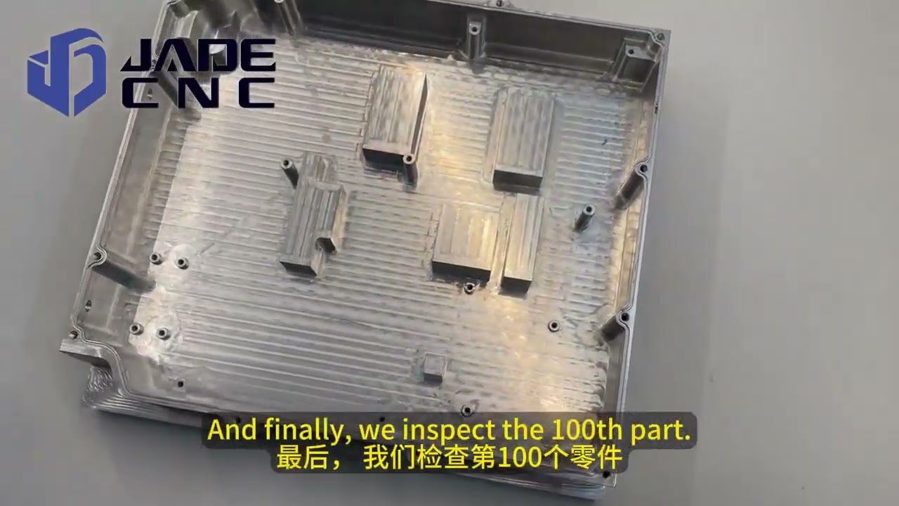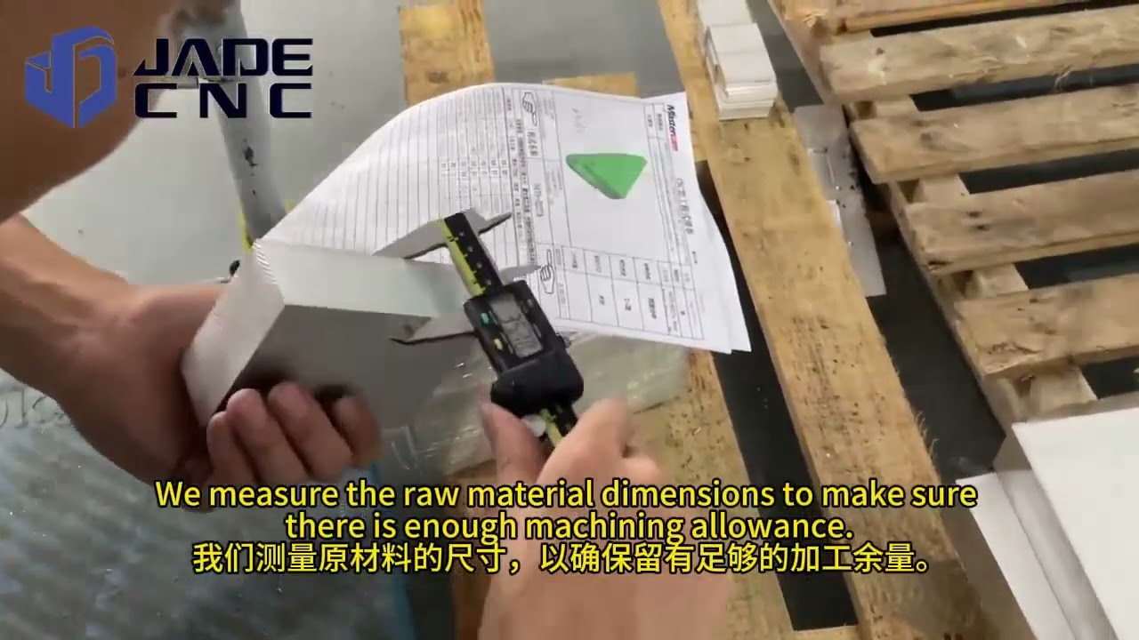


Why CNC Machining Deformation Creates Hidden Cost
CNC machined parts can become dimensionally unstable after rapid material removal, aggressive clamping, cutting heat, or prolonged storage. This risk is especially high in complex aluminum housings, thin-wall structures, large internal cavities, and elongated components. A first article inspection (FAI) may pass, yet subsequent parts can drift out of tolerance if dimensional stability is not maintained throughout the manufacturing process flow. This drift can lead to batch-level quality risk, rework, and delayed delivery.
At JADE-CNC, we treat CNC machining deformation control as an upfront process planning parameter rather than a downstream final inspection issue. Internal controlled sample data shows how structured material sourcing, adaptive fixturing, optimized machining toolpaths, temporary gypsum filling support, and inspection after thermal stabilization can reduce deformation-related variation.
Performance Comparison Before and After the Deformation Control Program
Metric | Before Control | After Control | Improvement |
Deformation-related reject rate | 18.5% | 2.3% | ↓ 87.6% |
Avg. flatness of 200 x 150 mm Al housing | 0.14 mm | 0.04 mm | ↓ 71.4% |
First-pass yield, thin-wall parts (<= 2 mm) | 62% | 94% | ↑ 51.6% |
Avg. rework cycle per batch | 3.2 days | 0.5 days | ↓ 84.4% |
This guide examines five common mechanisms behind aluminum CNC parts warping, explains how temporary industrial gypsum filling supports weak cross-sections during milling, and outlines a multi-stage process control method for improving dimensional stability across production lots.
Five Typical Machining Deformation Types in Aluminum CNC Components
From a practical process control perspective, dimensional errors in aluminum CNC parts generally originate from five clear categories. Understanding these root causes is vital for executing effective methods to prevent CNC machining deformation:
Overview of Five Typical Machining Deformation Types
Deformation Type | Common Symptoms | Primary Cause | Key Control Methods |
Raw Material Residual Stress | Warping, twisting, or bending immediately after roughing | Residual stress release from plate/bar stock | Select stabilized materials (T651), age after roughing, apply symmetric material removal |
Fixturing & Clamping Stress | In-tolerance while clamped, out-of-tolerance when released | Excessive clamping forces, inadequate physical support | Reduce clamping force, add auxiliary supports, optimize contact points |
Cutting Force Deflection | Component bends or bows after machining a single side | Heavy unilateral stock removal, uneven cutting forces | Implement layered toolpaths, symmetric milling, uniform step-down |
Thermal Expansion Drift | Dimensional drift during or immediately after long machining runs | Cutting friction heat, spindle growth, room temperature fluctuations | Use flood coolant, optimize cutting parameters, inspect only after thermal stabilization |
Thin-Wall Low Rigidity | Unstable wall thicknesses, poor flatness, profile deviation | Low geometric part rigidity | Separate roughing from finishing, leave uniform stock, utilize light finish cuts, design custom fixtures |
Managing Deformation Caused by Raw Material Residual Stress
This issue frequently compromises large plates, thin sheets, deep cavities, and complex structural frames. Consider a typical 6061-T651 aluminum plate scenario: the raw blank displays excellent flatness. However, once an operator mills 5 mm off the first face and unclamps the part, immediate warping begins. This twist does not indicate poor machine tool accuracy; it proves that the balance of inherent residual stress within the raw alloy block has been disrupted.
The Corrective Process Route
To preserve stability, avoid removing a large volume of material from a single side in one pass. Instead, deploy a balanced toolpath strategy:
Blank -> Rough Machine Side A -> Flip & Rough Machine Side B -> Symmetric Material Removal -> Leave Uniform Stock -> Stress Relief / Aging -> Semi-Finishing -> Final Thermal Stabilization -> Finishing Pass
For high-precision aerospace or medical components, a more rigorous sequence may be required:
Roughing -> Stress Relief (Natural or Artificial Aging) -> Semi-Finishing -> Re-Stabilization -> Precision Finishing
Why Material Sourcing Strategy Matters
Selecting the correct alloy temper is an easier way to mitigate aluminum CNC parts warping before a tool even touches the metal. Materials like 6061-T651 and 7075-T651 plates have undergone mechanical stretching to relieve internal stresses. The "51" suffix specifically designates a permanent mechanical stretch of 1% to 3% engineered to equalize internal forces.
Comparison of Common Aluminum Tempers and Residual Stress Levels
Material Temper | Treatment Method | Residual Stress Level | Typical Industry Applications |
6061-T6 | Solution heat treated + artificially aged | Relatively High | General structural parts, low-tolerance brackets |
6061-T651 | Solution treated + 1-3% stretch + aged | Low | Precision plates, deep cavity housings, manifolds |
7075-T6 | Solution heat treated + artificially aged | High | High-strength structural parts |
7075-T651 | Solution treated + 1-3% stretch + aged | Relatively Low | Aerospace structural parts, high-stress defense components |
6061-T652 | Solution treated + compression stress-relieved + aged | Low | Heavy-gauge thick plates, complex forgings |
Eliminating "False Dimensions" Caused by Fixturing and Clamping Force
Clamping deformation is a deceptive issue because it hides from operators on the shop floor. Imagine machining a thin-walled electronic housing:
- Measured while securely clamped in the vise: 100.00 mm (Perfect compliance)
- Inspected immediately after the toolpath completes: 100.01 mm (Within limits)
- Measured after releasing the vise jaws: 100.18 mm (Failed Out-of-Tolerance)
The raw workpiece was forcibly compressed by excessive clamping force during the milling cycle. The machine tool was effectively cutting a part trapped in a physically deformed state. Once released, the metal naturally sprang back to its true, non-compliant form.
Key Engineering Principle
Final part quality must be verified in its completely free, unconstrained state, never while under fixture clamping pressure.
Fixturing Deformation Control Methods Checklist
Control Method | Specific Workshop Practice | Applicable Sourcing Scenario |
Reduce Clamping Force | Apply the minimum necessary pressure required to hold the part during finishing passes. | All thin-wall components |
Add Support Points | Integrate adjustable auxiliary jacks or supports at overhanging locations. | Large deep cavities, thin-plate profiles |
Avoid Unsupported Clamping | Ensure a solid support block or locating pin sits directly beneath every clamping point. | All custom fixturing setups |
Clamp Near Rigid Supports | Align the clamping force line of action directly through the component's internal support faces. | Cantilevered part designs |
Use Soft Jaws | Machine custom aluminum or copper soft jaws to match the profile and increase surface contact area. | Round, cast, or highly irregular components |
Deploy Vacuum Chucks | Apply uniform, atmospheric large-area vacuum suction to prevent localized pinching. | Ultra-thin plates, flat sheet stock |
Build Dedicated Fixtures | Design custom conformal fixtures tailored exactly to the component's unique geometry. | Medium-to-high volume production batches |
It is critical to distinguish between roughing and finishing setups: roughing clamping pressure should never equal finishing clamping pressure. Before executing a final finish pass, operators must back off the clamps, allow the part to relax, and re-torque the system at a significantly lower pressure.
Mitigating Deflection Caused by Cutting Forces
Cutting force issues primarily appear when machining tall ribs, deep heat sinks, thin walls (<= 2 mm), and wide-area aluminum enclosures. When a cutting tool encounters a 2 mm wall, the lateral cutting forces physically push the thin sheet of metal away. The wall undergoes elastic deflection. Once the milling tool moves past, the metal springs back into place.
This dynamic results in highly variable wall thicknesses, tapered surfaces, out-of-spec perpendicularity, and localized dimensional steps.
Technical Tool and Parameter Tuning
The primary workflow logic requires roughing, leaving a uniform stock allowance, semi-finishing, and finishing with a light cut. Concurrently, use the following parameter adjustments to prevent thin-wall CNC milling deformation:
Tool and Parameter Optimization Points
Optimization Item | Technical Principle | Actionable Workshop Notes |
Tool Sharpness | Sharp cutting edges reduce friction and lower radial cutting forces. | Use polished, uncoated inserts optimized specifically for aluminum; swap worn tools early. |
Tool Diameter | Increasing tool diameter improves tool rigidity (Deflection proportional to L^3/D^4). | Select the largest possible tool diameter that internal corner radiuses allow. |
Tool Overhang | Minimizing tool extension reduces bending moments and eliminates chatter. | Keep tool overhang as short as the setup allows; use heat-shrink or hydraulic holders. |
Feed Rate | Feed per tooth governs chip load and corresponding tool pressure. | Keep feed rates within balanced chip-load limits; avoid excessive forces during wall finishing. |
Depth of Cut (a_p) | Axial depth of cut impacts total tool engagement. | For critical thin-wall finishing passes, keep a_p restricted to a tight 0.1 mm to 0.3 mm window. |
Width of Cut (a_e) | Radial engagement controls the lateral force vector. | Use a uniform, small a_e during finishing to prevent unilateral wall deflection. |
Toolpath Strategy | Selecting the correct milling direction stabilizes cutting pressures. | Utilize climb milling to direct forces into the machine table; utilize symmetric paths to balance forces. |
Controlling Dimensional Changes Caused by Cutting Heat
Aluminum alloys have a high coefficient of linear thermal expansion, typically about 23 x 10^-6 / deg C. To understand the practical scale of this effect, consider a large aluminum component with a baseline length of 500 mm. If the part changes temperature by 10 deg C due to cutting friction or environmental exposure, the theoretical dimensional change is calculated as:
Delta L = 500 mm x (23 x 10^-6/ deg C) x 10 deg C approx 0.115 mm
A 10 deg C thermal change can create a theoretical dimensional shift of about 0.115 mm. For precision engineering projects with tolerances at the +/-0.01 mm or +/-0.02 mm level, this thermal movement must be controlled before final inspection.
Theoretical Dimensional Shift of Aluminum Parts (mm)
Part Baseline Size | Delta T = 5 deg C | Delta T = 10 deg C | Delta T = 15 deg C | Delta T = 20 deg C |
100 mm | 0.012 mm | 0.023 mm | 0.035 mm | 0.046 mm |
200 mm | 0.023 mm | 0.046 mm | 0.069 mm | 0.092 mm |
300 mm | 0.035 mm | 0.069 mm | 0.104 mm | 0.138 mm |
500 mm | 0.058 mm | 0.115 mm | 0.173 mm | 0.230 mm |
800 mm | 0.092 mm | 0.184 mm | 0.276 mm | 0.368 mm |
Therefore, for high-precision components, operators cannot pull a hot part directly out of flood coolant, inspect it immediately on the CMM, and declare it compliant. The correct operational protocol requires:
Machining -> Component Cleaning -> Thermal Stabilization / Temperature Equalization -> Precision Inspection
Thermal Deformation Control Elements Checklist
Control Element | Specific Workshop Requirement |
Coolant Condition | Maintain a stable coolant concentration, volume, and high flow rate to evacuate heat instantly. |
Cutting Parameters | Manage heat generation by avoiding excessive tool dwell and maintaining proper chip clearing. |
Machining Cycle Time | For lengthy milling cycles, utilize inline machine thermal compensation macros to track axis drift. |
Environment Temperature | Maintain shop floor climate controls to limit ambient temperature variation within +/-2 deg C. |
Workpiece Temperature | Components must rest until they reach a stabilized ambient temperature before final inspection. |
Inspection Room Climate | High-precision metrology must be executed inside a laboratory calibrated to the standard 20 deg C reference. |
Spindle Thermal Growth | Run spindle warm-up cycles and ensure software parameters compensate for Z-axis thermal growth. |
Staged Processing for Ultra-Thin Walls and Large Internal Cavities
Machining components with ultra-thin walls and large internal cavities is one of the more difficult challenges in precision milling. Consider an aluminum block measuring 300 x 200 x 50 mm that must be machined into an electronic housing with a 2 mm wall and a 2 mm floor thickness. The total material removal rate (MRR) for this configuration can exceed 80% to 90%.
The workpiece begins its journey as an incredibly rigid solid block and finishes as a highly fragile, low-rigidity open shell. Even with an outstanding machine tool, perfect programming, and premium cutters, the release of material mass will trigger structural distortion. This problem cannot be bypassed by applying a single final finishing path; it demands a dedicated five-stage process architecture.
Five-Stage Machining Process for High-Cavity Components
Stage | CNC Operation Strategy | Stock Material Control | Primary Process Purpose |
Stage 1: Heavy Removal | Rapid rough milling to remove the bulk of internal core volume. | Leave a generous stock allowance of 0.5 mm to 1.5 mm. | Maximizes material removal efficiency while preserving structural block rigidity. |
Stage 2: Stress Relief | Unclamp the component, flip its orientation, re-fixture, and perform thermal or natural aging. | Maintain the baseline roughing stock envelope. | Allows heavy roughing-induced internal stresses to safely release. |
Stage 3: Semi-Finishing | Uniformly mill structural faces to homogenize the remaining stock layer. | Trim stock down to a precise 0.15 mm to 0.30 mm finishing allowance. | Eliminates non-uniform material steps, ensuring consistent tool pressure for the final pass. |
Stage 4: Stabilization | Unclamp the part entirely, allowing it to rest unconstrained until it reaches full thermal stabilization. | Maintain the tight semi-finish stock allowance. | Safely discharges secondary semi-finishing stresses and brings the alloy back to ambient room temperature. |
Stage 5: Precision Finishing | Apply high-speed, light-depth milling toolpaths to cut critical final dimensions. | Safely remove the remaining 0.15-0.30 mm stock to target print tolerances. | Improves surface finish, reduces geometric taper, and supports required dimensional precision. |
The fundamental philosophy guiding this five-stage system is clear: following every intense material removal phase, give internal stresses a window to release. Before hitting final print dimensions, verify the component has relaxed into a stable, stress-free state.
Conventional Anti-Deformation Methods vs. Gypsum Support Technology
Standard engineering techniques provide clear baseline benefits, but each conventional strategy has physical limitations when applied to thin-wall manufacturing:
Limitations of Conventional Anti-Deformation Methods
Method | Primary Function | Technical & Operational Limitation | Cost Impact |
Separating Rough & Finish Cycles | Leaves 1-3 mm of safety stock after roughing; delays finishing until after a stress-relief rest. | Adds secondary hand-offs and tracking; internal stresses can still release during final cuts. | +15% to 25% total cycle time |
Thermal Aging Treatments | Uses specialized batch ovens or resting periods to artificially normalize internal crystalline alignment. | Many job shops lack automated thermal ovens; natural resting lines require 2 to 4 weeks of floor space. | +0.50 to 2.00 per component |
Optimized Fixturing Clamps | Uses custom vacuum plates, soft jaw contours, and multi-point manual support jacks. | Designing intricate mechanical fixtures incurs heavy engineering costs; cannot support internal pocket walls. | +200 to 800 fixed tooling cost |
Cutting Parameter Scaling | Scales down axial depth of cut (a_p) while elevating spindle RPMs to drop physical tool pressure. | Drastically reduces material removal rates (MRR); cannot fully damp thin-wall cutting chatter. | +10% to 20% total cycle time |
The Critical Engineering Gap
When dealing with deep internal cavities and very thin walls (<= 3 mm), these conventional approaches may not provide enough internal structural rigidity. To address this limitation, JADE-CNC evaluates temporary backing techniques such as Industrial Gypsum Support Technology.
Executing the Gypsum Filling Process for Thin-Wall CNC Support
Core Process Principle
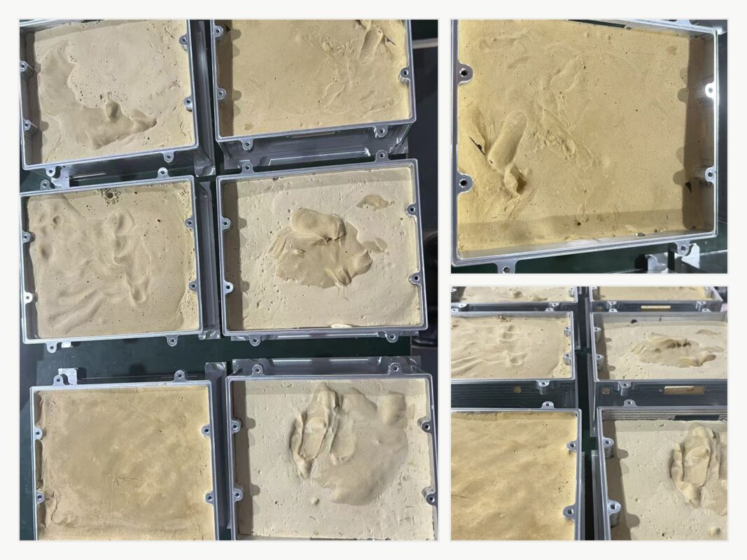
Temporary gypsum filling acts as a high-density, removable auxiliary backing structure. Before executing high-speed finishing paths on fragile or deep-pocket parts, JADE-CNC pours specialized, high-strength industrial gypsum into the raw internal cavities. Once cured, this medium provides an internal foundation directly behind the thin metal walls.
This solid support increases structural rigidity, reduces localized wall vibration, helps suppress tool chatter, distributes localized cutting heat, and can be flushed out after machining using a controlled water wash.
Technical Material Specifications of Filling-Grade Gypsum
Engineering Parameter | Technical Requirement & Specification |
Gypsum Material Type | alpha-calcium sulfate hemihydrate (Premium High-Strength Formulation) |
Compressive Strength (Dry, 2-Hour) | >= 35 MPa |
Flexural Strength (Dry, 2-Hour) | >= 8 MPa |
Initial Setting Window | 8 to 12 Minutes |
Final Curing & Setting Window | 25 to 40 Minutes |
Recommended Water-to-Powder Weight Ratio | 0.60 to 0.75 |
Linear Volumetric Expansion Post-Set | <= 0.15% |
Maximum Safe Drying Temperature Limit | <= 60 deg C (Exceeding this value prompts thermal cracking and degradation) |
Material Solubility in Water (at 20 deg C) | ~ 2.4 g/L (Naturally softens, breaks down, and flows out under water pressure) |
Gypsum Filling Material Applicability Matrix
Component Structural Type | Target Wall Thickness Range | Sourcing Recommendation | Expected Flatness & Profile Improvement |
Aluminum Thin-Wall Housing | 1.0 mm to 3.0 mm | Strongly Recommended | 60% to 80% Reduction in Deviation |
Thin-Walled Rings & Frames | 1.5 mm to 4.0 mm | Recommended | 40% to 60% Reduction in Deviation |
Elongated Thin Plates (L/t > 50) | 2.0 mm to 5.0 mm | Recommended | 30% to 50% Reduction in Deviation |
Complex Irregular Hollow Castings | 1.0 mm to 2.5 mm | Strongly Recommended | 50% to 70% Reduction in Deviation |
Solid Blocks & Thick-Walled Elements | > 8.0 mm | Not Required (Inherent Rigidity) | Not Applicable (N/A) |
Manufacturing Caveats & Engineering Review Limits
Gypsum filling is a targeted optimization option, not a universal manufacturing fix. It must be carefully evaluated if the component features blind micro-holes, complex internal fluid paths, open porous surfaces, strict absolute zero-residue chemical limits, or post-process medical cleanliness requirements. For these specialized projects, JADE-CNC runs comprehensive validation reviews:
- Path Verification: Ensure every filled pocket can be accessed by post-machining high-pressure wash nozzles.
- Thread Protection: Mask every threaded hole, critical sealing face, and precise datum surface with liquid silicone plugs prior to pouring.
- Chemical Compatibility: Confirm gypsum trace elements will not contaminate subsequent surface chemical treatmentslike Type III hard-coat anodizing, passivation, or aerospace bonding.
- Borescope Inspection: Use optical borescopes to inspect blind internal cross-holes after cleanout and verify that residue has been removed.
Step-by-Step Gypsum Tooling Operating Procedure
- Step 1: Cavity Pre-Treatment (10-15 Minutes)
Thoroughly degrease the internal cavity, removing all trace cutting fluids, machining oils, and loose aluminum chips. Seal precision features, blind threads, and locating datums using specialized high-temperature tape or silicone masking plugs. The cavity must be completely dry; any trapped moisture at the metal-gypsum boundary will generate micro-voids and ruin the backing support.
- Step 2: Slurry Mixing (5-8 Minutes)
Measure out the high-strength gypsum powder and water using the engineered weight ratio (0.60 to 0.75). Always add the powder smoothly into the water container (never pour water directly into dry powder) and stir slowly for 60 to 90 seconds to avoid introducing air. For best results, place the mixture in a vacuum degassing chamber for 30 to 60 seconds to eliminate up to 70% of micro-bubbles.
- Step 3: Pouring & Thermal Curing (2-4 Hours Total)
Pour the liquid slurry into the masked component cavity in a slow, steady stream. Continually tap the exterior aluminum walls with a soft mallet to force air bubbles to rise and escape. For deep configurations (> 50 mm), pour the gypsum in progressive 2-3 layer steps, allowing 15 to 20 minutes of setting time between passes. Let the component cure naturally at room temperature (20-25 deg C, 40-60% RH) for 2 to 4 hours. For expedited schedules, cure the assembly in an oven at 50-55 deg C for 45 to 60 minutes (do not exceed 60 deg C).
- Step 4: Machining Optimization
Begin the toolpath entries from solid metal boundaries rather than plunging directly down into the cured gypsum to avoid face chipping. After rigidity is verified, cutting parameters may be increased compared with unbacked thin-wall parts, depending on part geometry and setup stability:
Cutting Parameter Comparison: Unfilled vs. Gypsum-Filled (Aluminum Thin-Wall Finishing)
Parameter | Unfilled Thin-Wall | Gypsum-Filled | Net Production Increase |
Spindle Speed (S) | 8,000 rpm | 10,000 - 12,000 rpm | up 25% - 50% |
Feed Rate (F) | 800 mm/min | 1,200 - 1,500 mm/min | up 50% - 88% |
Axial Depth of Cut (a_p) | 0.3 mm | 0.5 - 0.8 mm | up 67% - 167% |
Radial Width of Cut (a_e) | 0.5 mm | 0.8 - 1.2 mm | up 60% - 140% |
- Step 5: Removal and Cleanout (15-30 Minutes)
Submerge the machined workpiece into a temperature-controlled warm water bath (35-45 deg C) for 15 to 20 minutes; the hydrated gypsum matrix naturally softens and breaks down. Use an industrial high-pressure water gun (3 to 5 bar) to flush the loose slurry out of internal channels. For complex features, pass a soft nylon brush across the area to clear surface residues. Conclude by rinsing the component with high-purity isopropyl alcohol (IPA, >= 95% concentration) to drive off water. Inspect all blind tapped holes and critical mating datums under 10x optical magnification to verify cleanliness before final inspection.
Production Case Study
- Component Analyzed: Aluminum 6061-T6 thin-wall communication electronics housing.
- Physical Dimensions: 200 x 150 x 80 mm with a nominal wall thickness of 2.0 mm.
- Engineering Quality Blueprint Target: Top face flatness tolerance <= 0.05 mm.
Machining Results Comparison: Without vs. With Gypsum Filling (n = 20 Parts)
Measurement Metric | Without Gypsum Support | With Cured Gypsum Filling |
Average Component Flatness | 0.142 mm | 0.038 mm (Passed) |
Best-Case Flatness Recorded | 0.080 mm | 0.020 mm |
Worst-Case Flatness Recorded | 0.210 mm | 0.060 mm |
Blueprint Quality Pass Rate (<= 0.05 mm) | 25% (5 out of 20 parts) | 95% (19 out of 20 parts) |
Average Surface Roughness (R_a) | 1.8 um | 0.8 um (Superior Finish) |
Total Machining Cycle Time Per Part | 42 Minutes | 28 Minutes (Fast MRR) |
While gypsum tooling adds roughly 30 minutes of combined auxiliary handling, mixing, and cleanout time per component, the added support can reduce finishing instability and lower rework risk. For suitable thin-walled structures, the process can improve dimensional consistency and reduce total production cost per accepted part.
The JADE-CNC Five-Stage Structural Deformation Control System
Temporary gypsum filling is one element of a broader manufacturing framework. To improve lot compliance, JADE-CNC integrates deformation-control methods into a documented five-stage production quality system:
Stage 1: Incoming Material Control
Incoming Material Inspection Control Standards
Control Item | Technical Standard Target | Inspection Methodology | Evaluation Frequency |
Material Certificate | EN AW-6061/7075, T6/T651 stable temper | Mill trace documentation review | Every incoming lot batch |
Incoming Plate Flatness | <= 0.5 mm / m | Precision straightedge + feeler gauge | 100% of incoming stock plates |
Pre-Aging Storage | Stable 20 - 25 deg C ambient environment | Automated warehouse climate logger | Continuous tracking |
Stress Relief Verification | Hardness variation delta <= +/- 5 HB | Brinell hardness point test | 1 structural sample per 500 kg |
Stage 2: Process Planning & CAM Strategy
Process Planning Deformation Control Rules
Engineering Planning Rule | Operational Core Specification |
Roughing Stock Allowance | Maintain 1.0 mm to 3.0 mm of buffer per side (geometry and mass dependent). |
Inter-Operational Stress Relief | Execute natural environmental resting, or run artificial thermal oven aging at 120 deg C for 4 hours. |
Finishing Toolpath Strategy | Program symmetric, multi-layered material removal; alternate cutting planes step-by-step. |
Feature Machining Sequence | Machine inherently high-rigidity blocks first; conclude with fragile low-rigidity features. |
Final Finishing Stock Envelope | Limit remaining material to a tight 0.15 mm to 0.30 mm layer per side. |
Thin-Wall Workpiece Route | Enforce a strict 5-stage progression: Heavy Removal -> Stress Relief -> Semi-Finish -> Stabilize -> Finish. |
Stage 3: Adaptive Fixturing and Structural Support
Fixturing and Auxiliary Support Solutions by Part Type
Part Structural Category | Primary Workholding Method | Secondary Auxiliary Support |
Flat Structural Plates (< 5 mm thick) | Uniform vacuum plate chucks | Direct atmospheric face contact |
Thin-Wall Complex Housings | Custom aluminum soft jaws + top clamps | Internal high-strength gypsum filling |
Rings and Thin Circular Profiles | 3-jaw pie-shaped full-contact soft jaws | Complete concentric support clamping |
Long Cylindrical Structures | Multi-vise arrays (3 to 5 distinct points) | Dead centers and steady rests between spans |
Irregular / Organic Castings | Custom multi-axis fixtures (CNC resin/alloy) | Gypsum filler or encapsulated low-melt alloy |
Large-Cavity Enclosures | Rigid dedicated conformal tooling plates | Internal gypsum filling + multi-point jack screws |
Stage 4: Machining Parameter Standardization
Standard Cutting Parameters for Common Engineering Materials
Material Grade | Operation Target | Spindle (rpm) | Feed (mm/min) | a_p (mm) | a_e (mm) | Coolant Strategy |
Al 6061-T6 | Bulk Roughing | 6,000 - 8,000 | 1,500 - 2,000 | 1.0 - 2.0 | 8.0 - 12.0 | High-Volume Flood |
Al 6061-T6 | Thin-Wall Finish | 10,000 - 12,000 | 1,200 - 1,500 | 0.3 - 0.5 | 0.5 - 1.0 | Air Blast + MQL |
Al 7075-T6 | Bulk Roughing | 5,000 - 7,000 | 1,200 - 1,600 | 0.8 - 1.5 | 6.0 - 10.0 | High-Volume Flood |
SUS304 Stainless | Heavy Roughing | 2,500 - 3,500 | 400 - 600 | 0.5 - 1.0 | 3.0 - 5.0 | High-Pressure Flood |
SUS304 Stainless | Fine Finishing | 3,500 - 4,500 | 300 - 500 | 0.15 - 0.3 | 0.3 - 0.5 | Minimum Quantity (MQL) |
Ti-6Al-4V Titanium | Heavy Roughing | 2,000 - 3,000 | 200 - 400 | 0.5 - 1.0 | 2.0 - 4.0 | Through-Spindle Flood |
Ti-6Al-4V Titanium | Fine Finishing | 3,000 - 4,000 | 150 - 300 | 0.1 - 0.2 | 0.2 - 0.4 | Precision MQL |
Stage 5: Advanced Metrology and Verification
Deformation Control Inspection Process and Acceptance Criteria
Metrology Step | Operational Timing | Equipment Deployed | Engineering Acceptance Criterion |
In-Process Dimensional Gate | Following individual high-MRR runs | Digital calipers & micrometers | Track within +/-0.02 mm of setup nominals |
Post-Machining Rest Phase | Prior to staging final CMM cycles | Climate-controlled rack | Stay unconstrained >= 4 hours at 20+/-2 deg C |
Final CMM Metrology | Post structural relaxation window | Zeiss CMM (0.001 mm res) | Strict adherence to drawing GD&T frames |
Flatness Profile Sweep | Final quality sign-off gate | CMM multi-point matrix scan | Meet print requirements (typically <= 0.05 mm) |
24-Hour Stability Recheck | Pre-packaging gate (Critical parts) | Zeiss CMM checking runs | Total structural dimension drift <= 0.005 mm |
Surface Finish Profilometry | Final visual quality audit | Stylus profilometer surface scan | Verify R_a matches print (typically 0.8 - 1.6 um) |
Free-State Relaxation Test | Immediately following clamp release | CMM vs. on-fixture readings | Total deviation from clamped state <= 0.01 mm |
Material Playbook: Deformation Control Strategies by Alloy
Different engineering alloys react differently to thermal and mechanical cutting stresses. JADE-CNC uses material-specific process guidance to target flatness over a standard 200 mm span:
Deformation Control Strategies and Achievable Precision for Common Materials
Material Grade | Primary Distortion Risk Vector | Primary Mitigation Strategy | Secondary Mitigation Strategy | Typical Achievable Flatness (200 mm span) |
Al 6061-T6 | High thermal expansion, rapid stress release | Artificial aging + gypsum cavity filling | High-speed machining parameters (force heat into chips) | 0.03 - 0.05 mm |
Al 6061-T651 | Lower residual stress, low wall mass instability | Symmetric material removal + separated rough/finish cycles | Thermally stabilized environment inspection | 0.02 - 0.04 mm |
Al 7075-T651 | High grain tension, prone to aggressive twisting | Double aging treatments (pre & post-roughing) | Dynamic symmetric toolpath balancing | 0.04 - 0.08 mm |
SUS304 Stainless | Severe work hardening, intense cutting forces | Polished sharp tooling, light a_p, high flood pressures | Post-roughing stress relief annealing cycles | 0.05 - 0.10 mm |
SUS316L Stainless | High cutting forces, local thermal grouping | Mirror parameters of SUS304 | Constant tool engagement paths | 0.05 - 0.10 mm |
Ti-6Al-4V Titanium | Ultra-low elastic modulus (spring-back), poor heat sink | Ultra-rigid mechanical fixtures, small a_p, deep flood volume | Low-stress cycloidal roughing toolpaths | 0.08 - 0.15 mm |
Copper (C11000) | Extreme softness, prone to mechanical crushing | Low-torque clamping setups, custom face-contact soft jaws | Final single-pass skim cut at minimal vise pressure | 0.03 - 0.06 mm |
Brass (C36000) | Low rigidity, internal structural tension | Standard 5-stage process routing | Sharp-edge unground cutters | 0.02 - 0.05 mm |
Quality Data Analysis from Controlled SPC Production Samples
JADE-CNC tracks deformation-critical dimensions via automated Statistical Process Control (SPC) charting across mid-to-high volume production batches. This internal capability log from Q2 2026 highlights the stability achieved using our multi-stage system:
Process Capability Index (C_pk) by Component Category - Q2 2026
Component Structural Category | Parts Inspected | C_pk (Flatness Profile) | C_pk (True Position) | Observed Lot Reject Rate |
Al Thin-Wall Housings (1-3 mm) | 1,240 | 1.42 | 1.55 | 1.8% |
Al Structural Plates (5-10 mm) | 860 | 1.68 | 1.72 | 0.7% |
Al Large-Cavity Components (MRR > 80%) | 420 | 1.31 | 1.40 | 4.2% |
Precision Stainless Steel Components | 520 | 1.25 | 1.38 | 3.1% |
Aerospace Titanium Components | 180 | 1.12 | 1.20 | 5.6% |
Precision Copper / Brass Components | 340 | 1.55 | 1.60 | 1.2% |
An industry standard C_pk >= 1.33 represents a capable manufacturing process when the measurement system and tolerance definition are appropriate. High-cavity aluminum parts (where material removal exceeds 80%) remain the most complex challenge due to the large loss of structural cross-sectional rigidity. However, by deploying our 5-stage progression paired with temporary gypsum tooling backing, production can remain within a more stable process window.
Frequently Asked Questions
What causes deformation in CNC machining?
Machining deformation is driven by four primary variables: the release of raw material residual stress, mechanical distortion from excessive or unsupported clamping forces, tool deflection caused by high cutting loads, and thermal volumetric expansion from cutting friction or shop environment temperature swings.
When is gypsum filling useful for CNC machining?
Gypsum encapsulation is recommended for thin-walled enclosures, thin-plate geometries (L/t > 50), deep open cavities, and delicate hollow frames where conventional clamping or vacuum fixtures cannot prevent wall vibration and part deflection during finishing toolpaths.
Can gypsum filling be used for every thin-wall part?
No. Gypsum filling must be avoided if a component contains inaccessible blind micro-holes, complex internal fluid channels that prevent complete cleanout, or if the material chemistry reacts poorly to water. It is also restricted if downstream specifications permit zero residual trace elements.
How do you completely clean out gypsum after machining?
The workpiece is immersed in a warm water bath (35-45 deg C) to soften and break down the binding agent. Internal cavities are then flushed out using a high-pressure water spray gun (3-5 bar). Finally, components pass through a multi-stage ultrasonic wash and a high-purity IPA rinse, then are verified under 10x optical magnification.
Partnering with JADE-CNC for High-Precision Machining
Controlling CNC machining deformation is not a matter of luck; it requires engineering controls across material selection, fixturing, thermal stabilization, and temporary backing techniques such as gypsum filling. By identifying deformation modes early, JADE-CNC uses controlled process planning to reduce deformation-related scrap and improve dimensional stability in high-precision components.
Are you experiencing high reject rates or warping issues with complex thin-walled structural parts? Contact the JADE-CNC Engineering Team to share your drawings, CAD files, material requirements, tolerance needs, surface finish requirements, quantity, and application details for process review.